Grizzly Vertical Mill G0667X Owner'S Manual Download Page 58

-56-

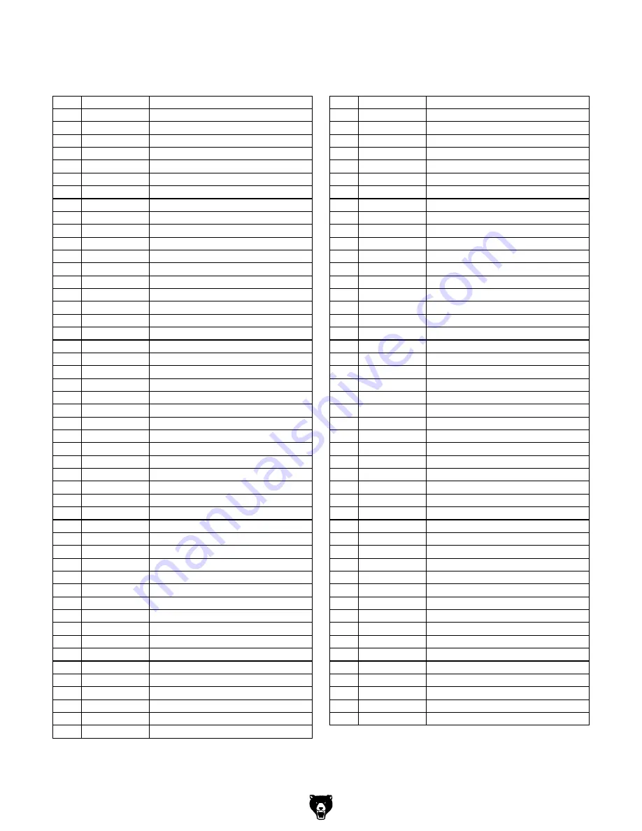
g0667X high precision Vs Vertical Mill

Head Parts List

REF PART #

DESCRIPTION

REF PART #

DESCRIPTION

101

P0667X0101

KNOB 3/8-16

150

P0667X0137A CLUSTER GEAR SHAFT 18/12T

102

P0667X0102

HANDLE

151

P0667X0137A FEED DRIVE CLUSTER GEAR 23T

103

P0667X0103

HANDLE HUB

152

P0667X0155A NEEDLE BEARING BZ66Z

104

P0667X0104

STEEL BALL 3/16

153

P0667X0153

REVERSE CLUTCH ROD

105

P0667X0105

COMPRESSION SPRING

154

P0667X0155A FEED REVERSE BUSHING

106

PSS05

SET SCREW 5/16-18 X 1/4

155A P0667X0155A FEED REVERSE GEAR ASSEMBLY

107

P0667X0107

PINION SHAFT SCREW

155

P0667X0155A FEED REVERSE BEVEL GEAR

108

P0667X0108

PINION SHAFT HUB SLEEVE

156

P0667X0156

FEED REVERSE CLUTCH

109

PSB33M

CAP SCREW M5-.8 X 12

157

P0667X0157

DOWEL PIN 3 X 20MM

110

P0667X0110

SPRING COVER

158

PR03M

EXT RETAINING RING 12MM

111

P0667X0111

COILED SPRING

159

P0667X0159

FEED WORM SHAFT BUSHING

112

PK155M

KEY 3 X 3 X 18

160

PK39M

KEY 3 X 3 X 10

113

P0667X0113

SPRING PIN

161

PK52M

KEY 3 X 3 X 15

114

P0667X0114

PINION GEAR SHAFT 10/16T

162

P0667X0162

FEED WORM SHAFT

115

PRIV001M

STEEL FLUTED RIVET 2 X 5MM

163

P0667X0163

FEED WORM SHAFT END CAP

116

P0667X0116

DATA PLATE

164

PSB06M

CAP SCREW M6-1 X 25

117

P0667X0117

ZERO SCALE

165

PSS01M

SET SCREW M6-1 X 10

118

P0667X0118

KNOB 1/4-20

166

P0667X0166

FEED GEAR SHIFTER FORK

119

P0667X0119

SHIFT CRANK

167

P0667X0167

CLUSTER GEAR SHIFT CRANK

120

PSS11

SET SCREW 1/4-20 X 1/4

168

P0667X0168

FEED SHIFT ROD

121

P0667X0121

COMPRESSION SPRING

169

P0667X0169

CLUSTER GEAR COVER

122

P0667X0122

INDENT PIN

170

P0667X0170

QUILL PINION SHAFT BUSHING

123

P0667X0123

SHIFT SLEEVE

171

P0667X0171

OVERLOAD CLUTCH GEAR 30T

124

P0667X0124

WORM GEAR CRADLE THROW-OUT

172

PR05M

EXT RETAINING RING 15MM

125

P0667X0125

WORM SHAFT

173A P0667X0173A OVERLOAD CLUTCH ASSEMBLY

126

PSS01M

SET SCREW M6-1 X 10

173

P0667X0173A OVERLOAD CLUTCH NUT

127

PK102M

KEY 4 X 4 X 18

174

P0667X0173A OVERLOAD CLUTCH

128

P0667X0128

WORM GEAR

175

P0667X0175

CLUTCH SPRING

129

P0667X0129

CLUSTER GEAR SHAFT CAP

176

PSS05M

SET SCREW M5-.8 X 10

130

P0667X0130

FEED CLUSTER GEAR 17/28/22T

177

P0667X0173A LOCK COLLAR

131

PR06M

EXT RETAINING RING 16MM

178

P0667X0178

CLUTCH RING

132

P0667X0132

BEVEL GEAR BUSHING

179

P0667X0179

CLUTCH WASHER

133

P0667X0133

BEVEL GEAR THRUST BUSHING

180

PR01M

EXT RETAINING RING 10MM

134

P0667X0134

FEED REVERSE BEVEL PINION

181

P0667X0181

CLUTCH RING SCREW

135

PK53M

KEY 3 X 3 X 45

182

P0667X0182

OVERLOAD CLUTCH TRIP LEVER

136

P0667X0137A FEED ENGAGE PIN

183

PRP03M

ROLL PIN 5 X 20

137A P0667X0137A WORM GEAR CRADLE ASSEMBLY

184

P0667X0184

CLUTCH ARM COVER

137

P0667X0137A WORM GEAR CRADLE

185

PSB79M

CAP SCREW M5-.8 X 35

138

PSS26M

SET SCREW M5-.8 X 6

186

PN05

HEX NUT 1/4-20

139

PSB04M

CAP SCREW M6-1 X 10

187

PSS06

SET SCREW 1/4-20 X 3/4

140

PW03M

FLAT WASHER 6MM

188

P0667X0188

COMPRESSION SPRING

141

P0667X0137A WORM GEAR SPACER

189

P0667X0189

OVERLOAD CLUTCH PLUNGER

142

P0667X0137A FEED DRIVE WORM GEAR 20T

190

P0667X0190

OIL CUP

143

P0667X0137A WORM CRADLE BUSHING

191

P0667X0191

FEED TRIP PLUNGER BUSHING

144

PK103M

KEY 3 X 3 X 12

192

P0667X0192

FEED TRIP PLUNGER

145

P0667X0137A FEED REVERSE BEVEL PINION

193

P0667X0193

FEED TRIP LEVER

146

PSB30

CAP SCREW 5/16-18 X 1/2

194

P0667X0194

FEED TRIP LEVER PIN

147

PW07

FLAT WASHER 5/16

195

PN04M

HEX NUT M4-.7

148

P0667X0137A FEED REVERSE BEVEL GEAR 24T

196

PSS49M

SET SCREW M4-.7 X 16

149

PK03M

KEY 3 X 3 X 8

Summary of Contents for Vertical Mill G0667X

Page 1: ...AL MILL w POWER FEED OWNER S Manual Copyright MAY 2008 By Grizzly Industrial Inc REVISED APRIL 2010 TS Warning No portion of this manual may be reproduced in any shape Or form without the written appr...

Page 2: ...personal protective equipment The manufacturer will not be held liable for injury or property damage from negligence improper training machine modifications or misuse Some dust created by power sandin...

Page 3: ...Oiler 68 Coolant System 69 Label Placement 70 WARRANTY AND RETURNS 73 INTRODUCTION 2 Foreword 2 Contact Info 2 Functional Overview 2 Identification 3 Machine Data Sheet 6 SECTION 1 SAFETY 9 Safety In...

Page 4: ...low Grizzly Industrial Inc C O Technical Documentation Manager P O Box 2069 Bellingham WA 98227 2069 Email manuals grizzly com Contact Info Functional Overview The Model G0667X vertical mill is used t...

Page 5: ...L M N O A Ram B Lifting Eye Bolt C Motor 3 HP 220V 3 Phase D Drive System E Emergency Spindle Brake F Quill G Spindle H Table I Longitudinal X Axis Ball Handle J Knee K One Shot Oiler L Machine Mount...

Page 6: ...el see Control Panel on Page 23 for more detail B Quill Auto Downfeed Controls see Fine Auto Downfeed Controls on Page 31 for more detail C Longitudinal Limit Switch D Table Lock E Saddle F Cross Feed...

Page 7: ...F G H I J K L A Belt Tensioning Lever B Ram Locks C Electrical Cabinet D Main Power Switch E Power Cord F Longitudinal X Axis Power Feed G Longitudinal Ball Handle H Coarse Downfeed Handle I Dial Ind...

Page 8: ...s Type Wood Crate Content Machine Weight 2352 lbs Length Width Height 58 x 54 x 73 in Electrical Power Requirement 220V Single Phase 60Hz Inverter Type Yaskawa V7AT23P7 Inverter Size 5 HP Switch ON OF...

Page 9: ...l 16 in Ram Travel 13 in Ram Swivel Angle 360 deg Head Travel 5 in Head Swivel Left and Right 90 deg Head Tilt Left and Right 45 deg Turret Or Column Swivel 360 deg Max Dist Spindle To Column 19 in Ma...

Page 10: ...Column Const Meehanite Cast Iron Base Const Meehanite Cast Iron Paint Urethane Other Collars Calibrated 0 220 in rev Other Specifications Country Of Origin Taiwan Warranty 1 Year Serial Number Locatio...

Page 11: ...ost types of dust wood metal etc can cause severe respiratory illnesses For Your Own Safety Read Instruction Manual Before Operating this Machine The purpose of safety symbols is to attract your atten...

Page 12: ...SURE GUARDS ARE IN PLACE AND WORK CORRECTLY BEFORE USING MACHINERY Safety Instructions for Machinery 16 REMOVE CHUCK KEYS OR ADJUSTING TOOLS Make a habit of never leaving chuck keys or other adjustme...

Page 13: ...ith damaged or worn parts Maintain your mill in proper working condition Perform routine inspec tions and maintenance promptly Put away adjustment tools after use 11 DISCONNECT POWER Make sure the mil...

Page 14: ...least a 14 gauge cord that does not exceed 50 feet in length The extension cord must also have a ground wire and plug pin A qualified electrician MUST size cords over 50 feet long to prevent motor dam...

Page 15: ...st 3000 lbs 1 Floor Mounting Hardware As Needed Items Needed for Setup Your machine was carefully packaged for safe transportation Remove the packaging materials from around your machine and inspect i...

Page 16: ...asher we will gladly replace them or for the sake of expediency replacements can be obtained at your local hardware store The unpainted surfaces are coated with a waxy oil to prevent corrosion during...

Page 17: ...sed around this machine Lock entrances to the shop or disable start switch or power connection to prevent unsupervised use Site Considerations Figure 7 Minimum working clearances 661 2 981 2 Moving Pl...

Page 18: ...Head Movement on Page 26 and Ram Movement on Page 27 for detailed instructions Figure 9 Using lifting straps to lift the mill 2 Position the lifting straps under the ram as shown in Figure 9 with padd...

Page 19: ...hods for mounting your machine and choose the best that fits your specific application Mounting to Shop Floor NOTICE Anchor studs are stronger and more per manent alternatives to lag shield anchors ho...

Page 20: ...w 3 Align the key on the leadscrew with the key way of the ball handle slide the assembly onto the leadscrew then secure it in place with the hex nut see Figure 12 Figure 12 Ball handle assembly insta...

Page 21: ...thread them into holes located on either side of the table see Figure 16 Figure 16 Coolant return hose installed Hose Clamp and Return Screen Elbow Connector Coolant Hose 8 Loosen the hose clamp push...

Page 22: ...n the machine 1 Make sure you understand the safety instruc tions at the beginning of the manual and that the machine is setup properly 2 Make sure all tools and objects used during setup are cleared...

Page 23: ...e main power switch safety feature is working cor rectly If the machine does start with the main power switch turned to OFF immediately disconnect power to the machine The main power switch safety fea...

Page 24: ...is essential to closely follow the proper break in procedures to ensure trouble free performance of your mill To perform the spindle break in procedure 1 Make sure the mill is turned OFF and the spin...

Page 25: ...this risk To reduce the risk of serious injury when using this machine read and understand this entire manual before beginning any operations Control Panel Refer to Figure 20 and the descriptions bel...

Page 26: ...al and cross feed ball handles are 0 001 The table moves 0 200 with each full revolution of the ball handles The graduated dial above the knee crank is in increments of 0 001 and the knee will move ve...

Page 27: ...ed is turned ON H Ball Handle Manually positions the table I Graduated Dial Marked in 0 001 incre ments each complete revolution is equal to 0 200 of longitudinal table travel Disengage the longitudin...

Page 28: ...head tilts 45 back and forth and rotates 90 from left to right see Figures 26 27 Figure 26 Head tilted 30 back Figure 27 Head tilted 45 to the left Tools Needed Qty Wrench or Socket 19mm 2 Tilting Hea...

Page 29: ...Always lock the ram firmly in place after adjusting its position If the ram and head moveunexpectedlyduringmillingoperations the cutter could bind with the workpiece and break apart resulting in perso...

Page 30: ...1 Determine the RPM needed for your workpiece 2 select the correct spindle speed range and 3 configure the spindle speed controls for the calculated RPM Calculating RPM 1 Use the table in Figure 32 to...

Page 31: ...o the desired position see Figure 34 Figure 34 Spindle speed range selector in the HIGH position Note You must press the selector handle in toward the head to retract the locking pin and move the hand...

Page 32: ...and rotate it clockwise to the forward DISENGAGE manual position see Figure 35 NOTICE To avoid damage to the quill auto downfeed gearing always rotate the selector clock wise 3 Align the pin in the h...

Page 33: ...uto Downfeed Components There are a number of devices that are used for fine downfeed and quill auto downfeed control Use Figure 37 and the descriptions below to understand the functions of these devi...

Page 34: ...the quill movement is downward the quill will automatically return to the top when the quill dog engages the auto downfeed stop and disengages the gearing If the quill movement is reversed with the d...

Page 35: ...t 5 Holding the tool in place insert the drawbar into the top of the head as shown in Figure 41 then thread it into the tool Figure 41 Drawbar inserted into the head 6 Tighten the drawbar into the too...

Page 36: ...o the machine for easy access Made for 5 8 T slots Figure 43 G1076 52 PC Clamping Kit H8368 Electric Power Drawbar Reduce your tool changing time to a fraction This easy to use Power Drawbar kit will...

Page 37: ...Spray G2870 Boeshield T 9 4 oz Spray H3788 G96 Gun Treatment 12 oz Spray H3789 G96 Gun Treatment 4 5 oz Spray T10063 Milling Vise 125 16 x 69 16 T10064 Milling Vise 171 8 x 83 4 Ultra precise in flatn...

Page 38: ...Page 38 Lubricate ram way Page 38 Schedule Use a brush and shop vacuum to remove chips and debris from the mill Never blow off the mill with compressed air as this will force metal chips deep into the...

Page 39: ...running from the one shot oiler feed lubrication to the ways of the column knee sad dle and table as well the longitudinal and cross feed leadscrews Pull the handle see Figure 50 and release it to sen...

Page 40: ...xpose the elevation leadscrew and grease fitting see Figure 54 Figure 54 Elevation leadscrew and grease fitting Leadscrew Grease Fitting Use mineral spirits and a shop rag to wipe the old grease and d...

Page 41: ...Qty Hex Wrench 3mm 1 To check the coolant level 1 DISCONNECT THE MILL FROM POWER 2 Clean away debris and grime from the res ervoir screen on the base of the mill then remove it to inspect the level of...

Page 42: ...l chips in the fluid the fluid can become a potent and extremely poisonous solution to humans and animals Use the correct personal protection equip ment when handling coolant to prevent infections and...

Page 43: ...lt 3 When moderate pressure is applied to the belt between the pulleys see Figure 60 there should be approximately 1 2 of belt deflection Pulley Deflection Pulley Figure 60 Checking for belt deflectio...

Page 44: ...ntacts correct the wiring 5 Replace fuse 6 Correct motor wiring connections Page 53 7 Replace relay switch 8 Ensure circuit size is suitable for this machine replace weak breaker 9 Test for power on a...

Page 45: ...1 Motor or component is loose 2 Pulley is loose 3 Motor mount loose broken 4 Machine is incorrectly mounted or sits unevenly 5 Motor fan is rubbing on fan cover 6 Chuck or cutter is at fault 7 Motor...

Page 46: ...re too loose 1 Tighten all locks on mill that are not associated with movement for the operation 2 Check that clamping is tight and sufficient for the operation make sure mill vise is tight to table 3...

Page 47: ...the gib When these adjustment screws are turned in opposite directions from each other the gib will be pushed back or forth to fill the loose void removing the play along the sliding surfaces Adjust t...

Page 48: ...ex Wrench 5mm 1 Hex Wrench 8mm 1 Wrench or Socket 19mm 1 To adjust leadscrew backlash 1 DISCONNECT THE MILL FROM POWER 2 Remove the front way cover 3 Move the table and saddle all the way for ward the...

Page 49: ...the bearing housing key graduated dial assembly and ball handle Note When re installing the bearing hous ing make sure the way cover mounting flanges see Figure 67 are on the top for proper alignment...

Page 50: ...e warranty 4 CIRCUIT REQUIREMENTS You MUST read and understand the CIRCUIT REQUIREMENTS section on Page 12 If you are unsure about the wiring codes in your area or you plan to connect your machine to...

Page 51: ...stand the Electrical Safety Instructions on Page 48 Electrical Panel Wiring Figure 70 Electrical panel wiring see Wiring Diagrams on Pages 50 51 Brake Resistor Transformer Fuses Main Power Switch Cabi...

Page 52: ...O 110V 5 15 Outlets View this page in color at www grizzly com T R R T R R R2 R2 T2 T2 R R R R T T T T 2R 1R 0 0 0 0 0 0 0 1 2 3 4 5 9 21 22 30 34 35 U2 W2 L1 L3 30 1 20 20 33 33 5 2 22 21 13 13 8 8 3...

Page 53: ...WARNING SHOCK HAZARD Disconnect power before working on wiring P2 S5 S6 S7 P1 R R FS FR FC MA MB MC S1 S2 S3 S4 SC PC S S AM AC RP R1 8 13 Bk Bk Bk Bk 40 Ohm Brake Resistor Variable Frequency Drive T...

Page 54: ...y Gy Purple Pr Gry Wht Gw Color Key Lt Green Lg Br Brown WARNING SHOCK HAZARD Disconnect power before working on wiring 3 NO 4 3 NO 4 3 NO 4 1 NC 2 Emergency Stop Motor Start Cutting Fluid ON OFF Spin...

Page 55: ...Spindle Motor 220V X1 U Y1 Z1 U2 V2 W2 V W 34 35 Rd Rd Cutting Fluid Pump Motor Rd 2 3 Spindle Brake Switch The motor wiring shown here is current at the time of printing but it may not match your mac...

Page 56: ...667X0011 SPANNER NUT 3 P0667X0003 BEARING CAP 12 P0667X0012 QUILL COVER 4 P0667X0004 SPACER 13 PSS26M SET SCREW M5 8 X 6 5 P7202 ANGULAR CONTACT BEARING 7207 14 P0667X0014 QUILL 6 P0667X0007A BUSHING...

Page 57: ...51 152 153 154 155 156 157 158 159 160 161 162 163 164 165 166 167 168 169 170 171 172 173 174 175 176 177 178 179 180 181 182 183 184 185 186 187 188 189 190 191 192 193 194 195 196 197 198 199 200 2...

Page 58: ...171 P0667X0171 OVERLOAD CLUTCH GEAR 30T 124 P0667X0124 WORM GEAR CRADLE THROW OUT 172 PR05M EXT RETAINING RING 15MM 125 P0667X0125 WORM SHAFT 173A P0667X0173A OVERLOAD CLUTCH ASSEMBLY 126 PSS01M SET S...

Page 59: ...PIN ASSEMBLY 206 PSB105 CAP SCREW 3 8 16 X 5 8 227 P0667X0227A KNURLED SHAFT 207A P0667X0207A SHIFTING ARM ASSEMBLY 228 P0667X0227A SHAFT PHLP HD SCREW 207 P0667X0207A SHIFTING ARM 229 P0667X0229 QUI...

Page 60: ...333 334 335 336 337 338 339 340 341 342 343 344 345 346 347 348 349 350 351 352 353 354 355 356 357 358 359 360 361 362 363 364 365 366 367 368 369 370 371 372 373 374 375 376 377 378 379 380 381 382...

Page 61: ...LOCK SHAFT 365 P0667X0365 PINION GEAR 26T 322 P0667X0322 SHAFT SLEEVE 366 PSS20M SET SCREW M8 1 25 X 8 323 PSS03M SET SCREW M6 1 X 8 367 P0667X0367 PINION GEAR SHAFT 324 PR47M EXT RETAINING RING 13MM...

Page 62: ...390 P0667X0390 MOTOR GEAR 44T 403 2 P0667X0403 2 EMERGENCY STOP SWITCH 391 P0667X0391 GEAR FLAT WASHER 403 3 P0667X0403 3 MOTOR START SWITCH 392 PSB31M CAP SCREW M8 1 25 X 25 403 4 P0667X0403 4 COOLA...

Page 63: ...0667X0525 RAM PINION SCREW 507 P0667X0507 INDICATOR PLATE 526 P0667X0526 TURRET 508 P0667X0508 WORM THRUST WASHER 527 P0667X0527 GIB ADJUSTMENT SET SCREW 509 P0667X0509 UPPER WORM LOCK COLLAR 528 PN08...

Page 64: ...5 616 617 618 619 620 621 622 623 624 625 626 627 628 629 630 631 632 633 634 635 636 637 638 639 640 641 642 643 644 645 646 647 648 649 650 651 652 653 654 655 656 657 658 659 660 661 662 663 664 60...

Page 65: ...CK PLUNGER 647 PK48M KEY 4 X 4 X 20 616 P0667X0615 KNEE LOCK PLUNGER 648 PSS02M SET SCREW M6 1 X 6 617 P51305 THRUST BEARING 51305 649 P0667X0649 BEVEL PINION 618 PK20M KEY 5 X 5 X 15 650 PSS03M SET S...

Page 66: ...723 724 725 726 727 728 729 730 731 732 733 734 735 736 737 738 739 740 741 742 743 744 745 746 747 748 749 750 751 752 753 701 702 711 710 709 713 713 711 710 735 704 705 706 707 708 709 731 732 733...

Page 67: ...9M EXT RETAINING RING 20MM 713 PK92M KEY 3 X 3 X 25 738 PSB06M CAP SCREW M6 1 X 25 714A P0667X0714A CROSS FEED LDSCR W NUT ASSY 739 PW03M FLAT WASHER 6MM 714 P0667X0714A CROSS FEED LEADSCREW 740 P0667...

Page 68: ...Y COVER REAR 818 P0667X0818 POWER FEED OPERATION MANUAL 813 P0667X0813 WAY COVER FRONT 819 PWR1214 WRENCH 12 14MM 814 P0667X0814 TOOL BOX 820 P0667X0820 CLOSED END WRENCH 19 21MM 815 P0667X0815 HEX WR...

Page 69: ...G0667X High Precision VS Vertical Mill 67 Electrical Cabinet Breakdown 901 901 1 902 903 904 905 906 907 908 909 910 911 912 913 914 915 916 917 918 919 920 907 1...

Page 70: ...0916 FUSE 1A 907 P0667X0907 RELAY OMRON MY4J 24V 917 P0667X0917 FUSE HOLDER 4 POS 907 1 P0667X0907 1 CONTROL RELAY SOCKET PYF 14A 918 P0667X0918 TRANSFORMER 500V 1PH 908 P0667X0905 CONTACTOR RIKEN RCR...

Page 71: ...OW 3 8 1202 PW03M FLAT WASHER 6MM 1211 P0667X1211 VALVE 1203 P0667X1203 COOLANT PUMP 1 8HP 220V 1PH 1212 P0667X1212 COOLANT NOZZLE 1204 P0667X1204 HOSE FITTING 1213 P0667X1213 ELBOW CONNECTOR 1 2 1205...

Page 72: ...LABEL HORIZ 1004 PLABEL 14 DISCONNECT POWER LABEL 1011 PLABEL 12B READ MANUAL LABEL HORIZ 1005 P0667X1005 MACHINE ID LABEL 1012 P0667X1012 TRAINED PERSONNEL ONLY LABEL 1006 PLABEL 55 ENTANGLEMENT HAZA...

Page 73: ...metalworker ____ 0 2 Years ____ 2 8 Years ____ 8 20 Years ____20 Years 6 How many of your machines or tools are Grizzly ____ 0 2 ____ 3 5 ____ 6 9 ____10 7 Do you think your machine represents a good...

Page 74: ...LINE FOLD ALONG DOTTED LINE GRIZZLY INDUSTRIAL INC P O BOX 2069 BELLINGHAM WA 98227 2069 Place Stamp Here Name_______________________________ Street_______________________________ City______________S...

Page 75: ...f Washington County of Whatcom We shall in no event be liable for death injuries to persons or property or for incidental contingent special or consequential damages arising from the use of our produc...

Page 76: ...Buy Direct and Save with Grizzly Trusted Proven and a Great Value Since 1983 ORDER 24 HOURS A DAY 1 800 523 4777 Visit Our Website Today For Current Specials...

Reviews: