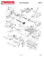
Figure 22. Gearbox area components.
Figure 23. Pulley area components.
Figure 24. Cutterhead installed in planer.
Model T32591 (Mfd. 05/21)
-7-
22. Turn speed selector switch counterclockwise
to speed "1" to grasp positioning pin with "U"
bracket.
23. Re-install screws removed from gearbox in
Step 24 on Page 3 of Removing Existing
Cutterhead instructions.
24. Test for smooth operation of speed selection
assembly by cycling speed selector switch
from "1" to "2" and then back to "1".
25. Re-install spacer on front roller.
26. Re-install sprockets and chain on front and
rear rollers (see
Figure 22).
27. Re-attach spring to chain tensioner. Verify
tensioner is engaged with chain, as shown in
Figure 22.
28. Re-install retaining rings on front and rear
rollers (see
Figure 22).
29. Re-install gearbox cover.
30. Re-install sprockets and chain on front and
rear rollers in pulley area (see
Figure 23).
31. Re-install chain tensioner and re-attach
spring. Verify tensioner is engaged with chain
(see
Figure 23).
32. Re-install pulley cover.
33. Re-install dust shroud into fan housing.
Note: DO NOT re-install cutterhead lock
lever! Cutterhead lock lever is not compatible
with the Model T32591.
34. Rotate dust shroud towards cutterhead.
Verify alignment arrow on fan housing aligns
with
CLOSED line on dust shroud.
35. Re-install red wing nuts on dust shroud.
36. Re-install top cover.
37. Remove any cardboard used to protect plan-
er table.
38. Connect machine to power and follow all
procedures outlined in your planer manual for
adjustment and calibration.
Chain Tensioner
Front Roller
Rear Roller
Spring
Chain
Chain Tensioner Assembly
Sprocket
Chain
Cutterhead Pulley
Sprockets
Retaining Rings


