


-42-
Model T28366 (Mfd. Since 04/18)
BUY PARTS ONLINE AT GRIZZLY.COM!
Scan QR code to visit our Parts Store.
97
96
95
94
93
39
99
101
100
43
42
41
40
52
76
58
92
50
57
77
65
78
86
85
55
53
54
88
87
56
80
82
49
79
83
84
69
68
67
70
61
74
73
72
71
64
63
62
89
66
81
60
59
75
90
91
51
44
45
46
47
48
102
60
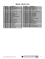
Headstock
REF PART #
DESCRIPTION
REF PART #
DESCRIPTION
39
PT28366039
EXT RETAINING RING 8MM
71
PT28366071
WORM GEAR 28T
40
PT28366040
LINKAGE BRACKET
72
PT28366072
KEY 8 X 7 X 20MM
41
PT28366041
FLAT WASHER 8MM
73
PT28366073
ARBOR SHAFT BUSHING
42
PT28366042
CAP SCREW M6-1 X 16
74
PT28366074
BALL BEARING 6006-2RS
43
PT28366043
RETAINING PIN
75
PT28366075
EXT RETAINING RING 25MM
44
PT28366044
GUARD LINKAGE (LOWER)
76
PT28366076
GASKET 47.5 X 1.8MM
45
PT28366045
EXT RETAINING RING 8MM
77
PT28366077
ARBOR SHAFT COVER
46
PT28366046
FLAT WASHER 8MM
78
PT28366078
CAP SCREW M6-1 X 16
47
PT28366047
RETAINING PIN
79
PT28366079
TENSION SPRING
48
PT28366048
GUARD LINKAGE (UPPER)
80
PT28366080
SET SCREW M6-1 X 10
49
PT28366049
SET SCREW M6-1 X 8
81
PT28366081
CAP SCREW M8-1.25 X 20
50
PT28366050
LOCK COLLAR
82
PT28366082
CAP SCREW M8-1.25 X 60
51
PT28366051
RETAINING PIN
83
PT28366083
HEX NUT M8-1.25
52
PT28366052
HINGE PIN
84
PT28366084
SPRING ARM (UPPER)
53
PT28366053
RETAINING PIN
85
PT28366085
FLAT WASHER 8MM
54
PT28366054
FLAT WASHER 8MM PLASTIC
86
PT28366086
STOP BLOCK CUSHION
55
PT28366055
FLAT WASHER 8MM
87
PT28366087
FLAT WASHER 6MM
56
PT28366056
SMALL GUARD LINKAGE (OUTER)
88
PT28366088
STOP BLOCK
57
PT28366057
RETAINING PIN
89
PT28366089
CAP SCREW M6-1 X 25
58
PT28366058
SMALL GUARD LINKAGE (INNER)
90
PT28366090
SPRING ARM (LOWER)
59
PT28366059
EXT RETAINING RING 8MM
91
PT28366091
CAP SCREW M6-1 X 16
60
PT28366060
FLAT WASHER 8MM PLASTIC
92
PT28366092
VISE BASE
61
PT28366061
BLADE GUARD (UPPER)
93
PT28366093
PIVOT SHAFT
62
PT28366062
BLADE HOOD
94
PT28366094
HINGE PIN
63
PT28366063
COOLANT CONTROL VALVE
95
PT28366095
CAP SCREW M6-1 X 35
64
PT28366064
PIPE FITTING
96
PT28366096
BUSHING PLASTIC
65
PT28366065
ARBOR SHAFT SEAT
97
PT28366097
BLADE FLANGE
66
PT28366066
ARBOR SHAFT SEAL
99
PT28366099
ROLL PIN
67
PT28366067
BALL BEARING 6006-2RS
100
PT28366100
BLADE GUARD (LOWER)
68
PT28366068
GASKET 56 X 2.65MM
101
PT28366101
CAP SCREW M10-1.5 X 30
69
PT28366069
ARBOR SHAFT BUSHING
102
PT28366102
CUTTING LABEL
70
PT28366070
ARBOR SHAFT