Model T27417 (Mfd. Since 09/15)
-29-
5. Remove nine M5-.8 x 12 Phillips head screws
(#33), lock washers (#27), and flat washers
(#21) that attach the base (#125) and table
tilt brackets (#43 & #45) to the tables (#30
& #41), then remove table tilt lock knobs
(#103).
6. Remove base (#125) from tables (#30 & #41)
to expose wheel support (#55), as shown in
Figure 36.
Drive Belt
Replacement
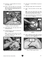
4. Remove two brown wires connected to recti-
fier (see
Figure 35).
Figure 35. Wires removed from rectifier.
Rectifier
Brown
Wires
The following procedure details removal and
replacement of the drive belts. Refer to the parts
breakdown and list to aid in proper identification of
parts referenced in the procedure.
Tools Required:
Qty
Screwdriver Phillips #2 ...................................... 1
Retaining Ring Pliers ......................................... 1
To replace drive belts:
1. DISCONNECT MACHINE FROM POWER!
2. Remove all sanding attachments and
backstop, then place sander upside down
on blocks, ensuring proper clearance of
spindle (#81).
3. Remove eleven M4 x 14 tap screws (#46)
from bottom guard (#134) shown in
Figure 34.
Figure 34. Sander turned upside down with
bottom guard removed.
Bottom
Guard
Figure 36. Housing base removed from cast-iron
table.
Tables
Wheel
Support
Summary of Contents for T27417
Page 44: ......


