


-44-
Model G0926 (Mfd. Since 11/20)
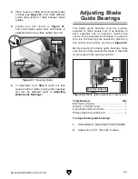
5. Adjust bearings as necessary to force blade
to be 90° to vise, then tighten hex nuts to
secure.
Note: Since bearings twist blade into posi-
tion, it is acceptable if there is 0.001"–0.002"
gap between blade and front or back of bear-
ing. Just make sure not to squeeze blade too
tightly with bearings. After guide bearings
are set, you should be able to rotate guide
bearings (although they will be stiff) with your
fingers.
6. Install front blade guide guard before resum-
ing operation.
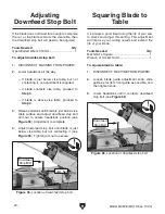
— If square evenly touches both face of vise
and blade, no adjustment is necessary.
— If square does not evenly touch blade
when evenly touching vise, proceed to
Step 4.
4. Loosen hex nuts securing eccentric bushings
attached to guide bearings (see
Figure 58).
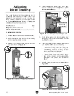
Note: There is a guard on front blade guide
assembly. Remove flat head screws shown
in
Figure 60 to remove guard and access
bushing.
Figure 60. Front blade guide guard.
Guard
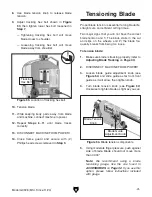
Figure 59. Square positioned against vise and
blade to check blade squareness.
3. Put square against face of vise and move it
over to blade (see
Figure 59).
Square
Summary of Contents for G0926
Page 56: ......


