Grizzly G0841 Owner'S Manual Download Page 6

-4-

Model G0841 (Mfd. Since 06/18)

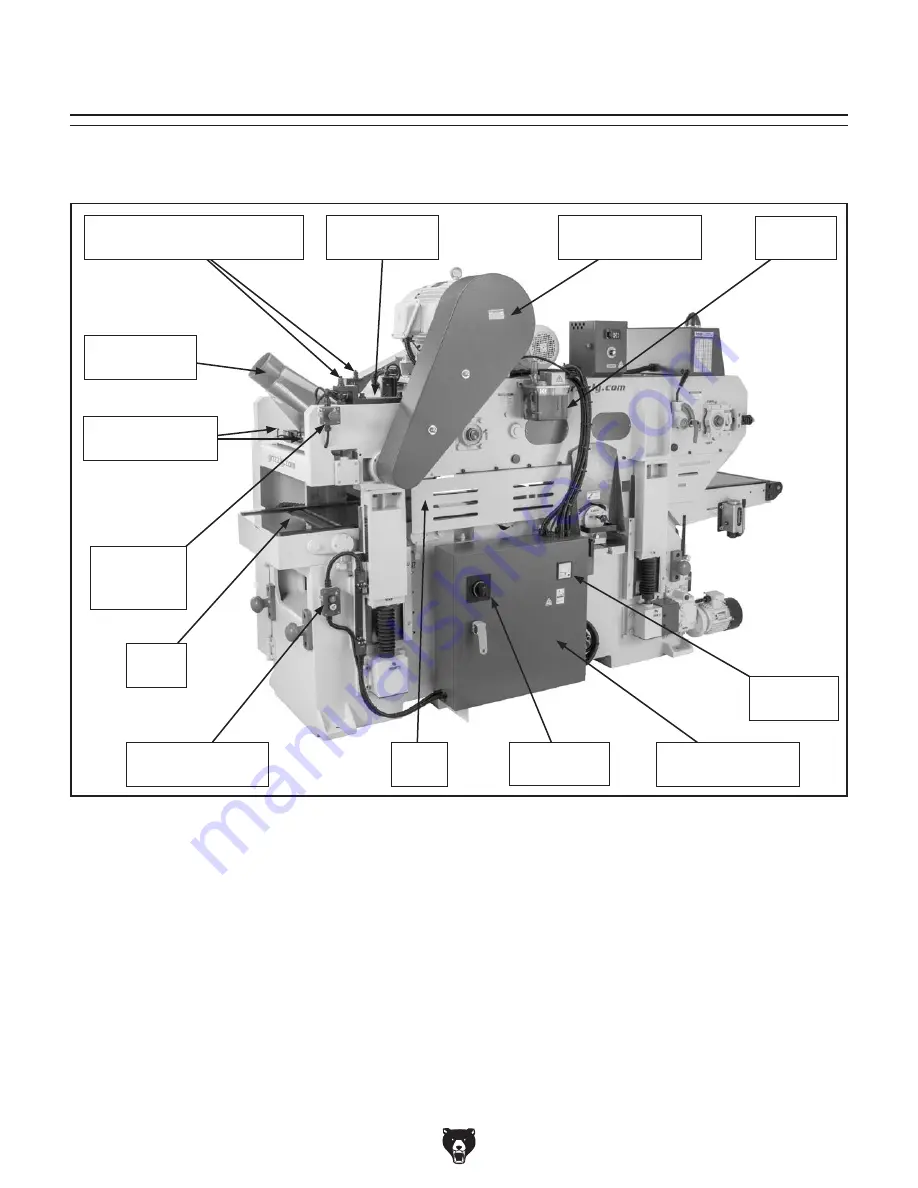
Identification (Rear)

Become familiar with the names and locations of the controls and features shown below to better understand 
the instructions in this manual.

Machine 

Amp Meter

Planer 

Table

Automatic 

Oiler

Chip Breaker 

Access Cover

Pressure Bar 

Adjustment Bolts 

Emergency 

Stop Button 

(1 of 2)

Electrical Panel w/

Lock-Out Handle

Table 

Guard

Adjustment Rods for 

Serrated & Pressure Rollers

Dust Hood w/ 

5" Dust Port

Upper Cutterhead 

Belt Cover

Headstock Height 

Switch (1 of 2)

Main Power 

Switch

Summary of Contents for G0841

Page 1: ...ER S MANUAL For models manufactured since 06 18 COPYRIGHT JULY 2018 BY GRIZZLY INDUSTRIAL INC WARNING NO PORTION OF THIS MANUAL MAY BE REPRODUCED IN ANY SHAPE OR FORM WITHOUT THE WRITTEN APPROVAL OF G...

Page 2: ...g grinding tool integrity and the usage of personal protective equipment The manufacturer will not be held liable for injury or property damage from negligence improper training machine modifications...

Page 3: ...w 32 Planing Tips 33 Workpiece Inspection 34 Wood Types 35 Cutting Problems 35 Setting Depth of Cut Lower Cutterhead 36 Setting Depth of Cut Upper Cutterhead 37 Adjusting Infeed Safety Guard 38 Using...

Page 4: ...de every effort to be exact with the instruc tions specifications drawings and photographs in this manual Sometimes we make mistakes but our policy of continuous improvement also means that sometimes...

Page 5: ...t Scale 1 of 2 No list of safety guidelines can be com plete Every shop environment is different Always consider safety first as it applies to your individual working conditions Use this and other mac...

Page 6: ...the instructions in this manual Machine Amp Meter Planer Table Automatic Oiler Chip Breaker Access Cover Pressure Bar Adjustment Bolts Emergency Stop Button 1 of 2 Electrical Panel w Lock Out Handle T...

Page 7: ...ols and features shown below to better understand the instructions in this manual 6 Dust Port Chain Drive Access Door Lower Cutterhead Belt Cover Chain Drive Serrated Roller Automatic Oiler Switch Upp...

Page 8: ...terhead requires 30 40 seconds to come to complete stop G Upper Cutterhead On Button Push to start upper cutterhead motor Upper cutterhead requires 5 15 seconds to reach full speed H Lower Cutterhead...

Page 9: ...workpiece thickness value while in Input mode U Numerical Key Pad Enter specific values for final workpiece thickness Press 0 9 and decimal keys as needed to enter desired final workpiece thickness Th...

Page 10: ...BDC of upper cutterhead to planer table AK Emergency Stop Button 1 of 2 Push to stop all machine functions and disable power button Remains in depressed position until manually reset Reset by twisting...

Page 11: ...ad belts and pulleys during operation Remove cover to access belts and pulleys for service maintenance AQ Automatic Oiler w Reservoir Slowly oils feed track gear and chain Machine Right AW Planer Tabl...

Page 12: ...ack Chain driven conveyor track that securely grabs holds and feeds workpieces into the lower cutterhead and toward the upper cutterhead Feed track has spring loaded fingers to grip workpieces B Infee...

Page 13: ...x Width x Height 110 x 47 x 70 in Must Ship Upright Yes Electrical Power Requirement 240V 3 Phase 60 Hz Full Load Current Rating 69 2A Minimum Circuit Size 100A Connection Type Permanent Hardwired to...

Page 14: ...umber of Cuts Per Inch 77 28 Cuts in Number of Cuts Per Minute 24 000 effective Cutterhead Speed 4000 RPM Planing Feed Rate 26 72 FPM Max Cut Depth Upper Cutterhead Full Width 3 16 in Max Cut Depth Up...

Page 15: ...Certified by a Nationally Recognized Testing Laboratory NRTL No Features Dual Spiral Cutterheads with 114 Indexable Cutters each Variable Feed Speed from 26 72 FPM Feed Belt with Spring Loaded Finger...

Page 16: ...proof DANGEROUS ENVIRONMENTS Do not use machinery in areas that are wet cluttered or have poor lighting Operating machinery in these areas greatly increases the risk of accidents and injury MENTAL ALE...

Page 17: ...moving parts or flying debris Make sure they are properly installed undamaged and working correctly BEFORE operating machine FORCING MACHINERY Do not force machine It will do the job safer and better...

Page 18: ...maged inserts WORKPIECE SUPPORT To reduce risk of kick back and jams always make sure workpieces can move completely across tables without rocking or tipping For long stock use auxiliary support stand...

Page 19: ...eating or fire may result especially if connected to an undersized circuit To reduce the risk of these hazards avoid over loading the machine during operation and make sure it is connected to a power...

Page 20: ...applicable electrical codes and ordinances Serious injury could occur if you connect machine to power before completing setup process DO NOT connect to power until instructed later in this manual Gro...

Page 21: ...setup process The following are needed to complete the setup process For Lifting and Moving Two additional people A forklift or other power lifting equipment rated for at least 7000 lbs Four lifting s...

Page 22: ...rials while unpack ing or they are pre installed at the factory Inventory Figures 10 11 Qty A Double Sided Planer 1 B Toolbox 1 C Adjustable Wrench 10 1 D Ratcheting Drive 1 4 w T 20 Torx Bits 5 1 E P...

Page 23: ...rea to minimize exposure to toxic fumes Before cleaning gather the following Disposable rags Cleaner degreaser WD 40 works well Safety glasses disposable gloves Plastic paint scraper optional Basic st...

Page 24: ...this manual See below for required space allocation Physical Environment The physical environment where the machine is operated is important for safe operation and lon gevity of machine components For...

Page 25: ...ure 15 and attach straps to lifting equipment with heavy duty shackles or other rigging equipment Cleats are positioned on machine to bal ance weight of machine when using four lifting straps of equal...

Page 26: ...ootings at corners of machine as shown in Figure 17 Make sure center of threaded hole in footing aligns with center of leveling pad 2 Insert 4 M16 1 5 x 75 hex bolts with 4 M16 1 5 jam nuts into 4 thr...

Page 27: ...o secure these adjustments This process will help machine components remain straight and flat Note For best results use a precision level that is at least 12 long and sensitive enough to measure movem...

Page 28: ...e The elevation system and feed system gearboxes and the automatic oiler and one shot oiler reser voirs must have the proper amount of oil in them before the machine can be operated IMPORTANT Damage c...

Page 29: ...cian as recommended is the primary means for disconnecting or connect ing the machine to the power source Electrocution fire shock or equipment damage may occur if machine is not properly grounded and...

Page 30: ...l all preceding setup instructions have been performed Operating an improperly set up machine may result in malfunction or unexpect ed results that can lead to serious injury death or machine property...

Page 31: ...motors and electrical systems Figure 28 Location of power button Power Button 8 Verify correct 3 phase power supply polarity by using headstock height switches see Figure 29 to raise and lower headsto...

Page 32: ...s working correctly Proceed to Step 16 If any motors or feed system DO START with Emergency Stop button pushed in immediately disconnect power to machine The Emergency Stop button safety feature is no...

Page 33: ...econds for cutterheads to come to complete stop Figure 34 Location of emergency stop plate 23 Repeat Steps 9 12 24 Use a pushstick or workpiece to push emer gency stop plate on front of machine see Fi...

Page 34: ...used by lack of training To complete a typical operation the operator does the following 1 Makes sure machine is disconnected from power 2 Examines workpiece to make sure it is suitable for planing re...

Page 35: ...to help ensure safe working conditions Plane ONLY natural wood fiber Do not plane wood composites or other materials that could break up in the planer and cause operator injury or damage to planer Ins...

Page 36: ...ow will plane poorly and cause excessive wear to the machine Excess moisture can also has ten rust and corrosion of the machine and or individual components Excessive Warping Workpieces with excessive...

Page 37: ...e rest of the board Usually caused when the workpiece is not prop erly supported as it goes through the machine In many cases however a small amount of snipe is inevitable Solution The best way to dea...

Page 38: ...iln dried KD Air dried AD lumber must be seasoned properly and have no surface moisture DO NOT surface partially air dried PAD lumber Make sure planer inserts are sharp Reduce depth of cut Rippled Cut...

Page 39: ...of material that is removed from the top of the workpiece as it passes underneath the upper cutterhead Setting Depth of Cut Upper Cutterhead Figure 41 Example of thickness planing Removed Surface Figu...

Page 40: ...andwheel for fine adjustment Use the headstock height switches see Figures 43 44 and the depth of cut scales see Figures 43 44 to set a final workpiece thickness Note Alternatively use the headstock h...

Page 41: ...thick ness is to use the digital control pad to enter a value and allow the machine to automatically set the headstock height The digital control pad remains in Input mode unless the headstock is movi...

Page 42: ...hickness to preset value Press key Headstock auto matically adjusts to preset final workpiece thickness and digital readout displays cur rent value in real time To increase final workpiece thickness b...

Page 43: ...operations or damage to the machine may result Figure 47 Location of feed rate dial Feed Rate Dial Adjusting Feed Track Pressure setting feed rate adjusting feed belt pressure If you notice the feed t...

Page 44: ...t pen to num ber V belts Lower Cutterhead Inserts Figure 49 Lower cutterhead belt cover opened Tension Lock Lever Belt Cover Tension Lever V Belts Pulley Figure 50 Location of lower cutterhead hex bol...

Page 45: ...2 Lubricate cutterhead carriage with a small amount of machine oil and then use handle to push lower cutterhead back into cutterhead carriage 13 Re install V belts belts Make sure ribs of belts are se...

Page 46: ...g a smooth finish with cutting operations Dirt or dust trapped under insert during instal lation will slightly raise insert in cutterhead which will leave marks on final workpiece Tip Use low pressure...

Page 47: ...indexable carbide inserts Figure 56 Rotacator Precision Planer Tool G1738 Rotacator Precision Planer Tool The Rotacator is a dial indicator on a magnetic base and is designed for quickly and accurate...

Page 48: ...0 Models D2273 and D2274 Roller Stands D2273 D2274 Figure 61 Model G0683HEP 10 HP Cyclone Dust Collector G0638HEP 10 HP Cyclone Dust Collector Equipped with a dual filtration HEPA filter sys tem Featu...

Page 49: ...s If you work around dust everyday a half mask respirator can be a lifesaver Also compatible with safety glasses H3631 H3635 Basic Hearing Protection H4978 Deluxe Earmuffs 27dB H4979 Twin Cup Hearing...

Page 50: ...s and motors Lubricate infeed table slideways see Page 53 Lubricate cutterhead bearings see Page 53 Check motor belts for tension damage or wear Check feed chain for tension damage or wear Inspect ent...

Page 51: ...ual could lead to premature failure of machine components and will void the warranty Use the information in the charts below as a guide for lubrication tasks We recommend using Grizzly Model T23962 T2...

Page 52: ...LGI 2 1 Pump Table Roller Bearings NLGI 2 1 Pump Feed System Gear box ISO 320 T28042 74 oz Elevation Gearbox ISO 320 T28042 17 oz Lubrication Amount Type Automatic Oiler Lube Type T26685 or ISO 32 Equ...

Page 53: ...rack roller bearings grease fittings leftside Grease Fittings Feed Track Bearings Slideways Lube Type T26419 or NLGI 2 Equivalent Lube Amount 1 Pump Lube Frequency 200 Hours Item s Needed Qty Grease G...

Page 54: ...tion slideways Chipbreaker Segments Lube Type T26685 or ISO 32 Equivalent Lube Amount 1 to 3 Drops Lube Frequency 200 Hours Item s Needed Qty Pump Type Oil Can 1 Shop Rags As Needed The chipbreaker se...

Page 55: ...l oil cup after oil passage is cleared infeed table slideways Cutterhead Bearings Lube Type T26419 or NLGI 2 Equivalent Lube Amount 2 Pumps Lube Frequency 700 Hours Item s Needed Qty Grease Gun 1 Shop...

Page 56: ...material rolls smoothly across the planer table The table roller bearings are lubricated by grease fittings see Figure 82 Wipe grease fittings clean and use a grease gun to pump a small amount of gre...

Page 57: ...ny excess oil then clean and replace vented fill plug Clear vented fill plug with low pressure compressed air if clogged Figure 83 Location of chain drive gearbox and components Vented Fill Plug Gearb...

Page 58: ...ctrical panel Page 28 Elevation system will not startup 1 Wiring open has high resistance 2 Component in motor s power circuit at fault 3 Magnetic contactor s at fault 4 Motor s at fault 1 Check fix b...

Page 59: ...inserts 10 Cutterhead s bearings at fault 11 Motor s bearings at fault 12 Feed system gearbox at fault 1 Re tighten component inspect replace damaged bolts nuts 2 Tension replace V belts Page 59 ensur...

Page 60: ...f cut 5 Rotate replace inserts Page 42 6 Clear blockages seal leaks move machine closer to dust collector upgrade dust collector Chipping consistent pattern 1 Knots or conflicting grain direction in w...

Page 61: ...ee Figure 85 Tensioning Lower Cutterhead V Belts Pulley Deflection Pulley 3 8 Figure 86 Correct belt deflection when properly tensioned 3 Check belt tension Each belt is correctly tensioned when there...

Page 62: ...secure motor to mounting plate see Figure 88 Item s Needed Qty Wrench Open Ends 14mm 2 Wrench Open Ends or Socket 17mm 2 Wrench Open Ends or Socket 19mm 1 Figure 87 Location of upper cutterhead V bel...

Page 63: ...structions 6 Re install lower cutterhead belt cover and close chain drive access door Replacing Upper Cutterhead V Belts To replace upper cutterhead V belts 1 DISCONNECT AND LOCK OUT MACHINE AT POWER...

Page 64: ...r person slide upper cutterhead motor towards rear of machine until there is slack between V belts and pulleys 7 Remove V belts and replace them with a matched set Make sure ribs of V belts belt are s...

Page 65: ...n hex nuts on hex bolts that secure motor to mounting plate see Figure 97 Upper Cutterhead Pulley Item s Needed Qty Wrench or Socket 14mm 2 Wrench or Socket 17mm 2 Wrench or Socket 19mm 1 Figure 95 Lo...

Page 66: ...tterhead Proper lower cutterhead alignment ensures an even cut across the entire workpiece during sur face planing To check and align lower cutterhead height 1 DISCONNECT AND LOCK OUT MACHINE AT POWER...

Page 67: ...rhead height is achieved 9 Tighten hex bolts and jam nuts to secure car riage in position 10 Close lower cutterhead belt cover and chain drive access door 4 Place block gauge in each position shown in...

Page 68: ...in Figure 103 Note Make sure side B of block gauge is face down Item s Needed Qty Hex Wrench 5mm 1 Block Guage Supplied w Machine 1 5 Loosen cap screws that secure scale pointer to base see Figure 10...

Page 69: ...ger Planer Table Rotacator Prior to squaring the headstock and adjusting the upper cutterhead components the upper cutterhead must be set at Bottom Dead Center BDC as shown in Figure 105 Top Dead Cent...

Page 70: ...e headstock height is not 4 then determine which end is higher and pro ceed to Step 4 4 On end of machine where headstock is higher loosen 4 cap screws securing left side and rightside elevation leads...

Page 71: ...until leftside and rightside of headstock are even and then tighten 2 cap screws secur ing elevation leadscrew collar 9 Set headstock height Refer to Setting Headstock Height on Page 70 If inserts are...

Page 72: ...oller chipbreaker pressure bar and pressure rollers are set at the correct distance below the upper cutterhead inserts at Bottom Dead Center BDC It is also essential that the lower pressure rollers ar...

Page 73: ...t and height adjust ment bolt see Figure 112 Figure 111 Rotacator placed underneath left side of idler roller 6 Tighten or loosen height adjustment bolt as needed to set correct idler roller height an...

Page 74: ...rated roller see Figure 114 Figure 114 Rotacator placed underneath leftside of serrated roller Planer Table Rotacator Bottom of Serrated Roller 4 Slide Rotacator or dial indicator back and forth acros...

Page 75: ...117 Rotacator placed underneath first chipbreaker segment Planer Table Rotacator Bottom of First Chipbreaker Segment Adjusting Chipbreaker Upper Cutterhead BDC Bottom Dead Center Chipbreaker 0 000 0...

Page 76: ...r table underneath left side of pressure bar see Figure 120 Figure 120 Rotacator placed underneath left side of pressure bar Planer Table Rotacator Bottom of Pressure Bar 4 Slide Rotacator or dial ind...

Page 77: ...jam nut and hex nut on spring loaded height adjustment rod see Figure 124 Adjusting Upper Pressure Roller 0 020 0 028 Upper Cutterhead BDC Bottom Dead Center Upper Pressure Roller Figure 122 Correct...

Page 78: ...s Figure 126 Block gauge placed over front lower pressure roller Figure 127 Block gauge side A 4 Place block gauge on planer table across one side of front lower pressure roller see Figure 126 Note Ma...

Page 79: ...tion chain To adjust elevation chain tension 1 DISCONNECT AND LOCK OUT MACHINE FROM POWER 2 Remove lower cutterhead belt cover and then loosen hex bolt next to lower cutterhead motor pulley see Figure...

Page 80: ...l startup always disconnect and lock out machine from power before adjustments maintenance or service To tension feed track 1 DISCONNECT AND LOCK OUT MACHINE FROM POWER 2 Measure length of both compre...

Page 81: ...metalworker ____ 0 2 Years ____ 2 8 Years ____ 8 20 Years ____20 Years 6 How many of your machines or tools are Grizzly ____ 0 2 ____ 3 5 ____ 6 9 ____10 7 Do you think your machine represents a good...

Page 82: ...LINE FOLD ALONG DOTTED LINE GRIZZLY INDUSTRIAL INC P O BOX 2069 BELLINGHAM WA 98227 2069 Place Stamp Here Name_______________________________ Street_______________________________ City______________S...

Page 83: ...shall be tried in the State of Washington County of Whatcom We shall in no event be liable for death injuries to persons or property or for incidental contingent special or consequential damages arisi...

Page 84: ......

Reviews: