-26-
Model G0733 (Mfg. Since 10/11)
Always choose the correct spindle speed
for an operation. using the wrong speed
may lead to the workpiece being thrown at
high speed, causing fatal or severe impact
injuries.
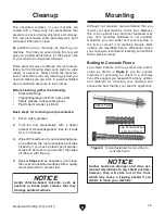
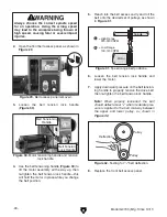
2. open the front belt access panel, as shown in
figure 29.
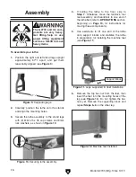
3. loosen the belt tension lock handle
(
figure 30).
figure 29. Belt access panel removed.
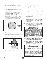
4. use the belt tensioning handle (figure 30) to
lift the motor assembly all the way up, then
re-tighten the belt tension lock handle—this
will hold the motor in place while you change
the belt position.
figure 30. motor tensioning handle and tension
lock handle.
Belt tensioning
handle
Belt tension
lock handle
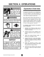
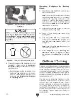
5. reach into the belt access cavity and roll the
belt onto the desired set of pulleys, as shown
in
figure 31.
6. loosen the belt tension lock handle and
lower the motor.
7. apply downward pressure on the belt tension-
ing handle to properly tension the drive belt,
then re-tighten the belt tension lock handle.
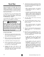
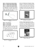
Note:
When properly tensioned, the belt
should deflect about
1
⁄
8
" when moderate pres-
sure is applied to the belt mid-way between
the upper and lower pulley, as shown in
Figure 32
.
8. replace the front belt access panel.
figure 32. testing for
1
⁄
8
" belt deflection.
Pulley
Deflection
Pulley
figure 31. speed range belt positions.
Spindle
Motor
B
A
A
= High Range
330-3200 RPM
B
= Low Range
100-1200 RPM
Summary of Contents for G0733
Page 52: ......


