Model G0733 (Mfg. Since 10/11)
-23-
To adjust the angle or height of the tool rest:
1. loosen the tool rest base lock lever and the
tool rest lock handle to adjust the position of
the tool rest.
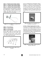
2. position the tool rest approximately
1
⁄
4
" away
from the workpiece and approximately
1
⁄
8
"
above the workpiece center line, as shown in
figure 21.
3. re-tighten the tool rest lock handle and the
tool rest base lock lever to secure the tool
rest in position.
Workpiece
Center Line
Distances
Tool Rest
1
⁄
8
"
1
⁄
4
"
figure 21. tool rest position relative to
workpiece.
installing/Removing
Headstock center
the included spur center installs into the head-
stock spindle with an mt#2 tapered fit.
installing the Headstock center
1. disCoNNeCt lathe From poWer!
2. make sure the mating surfaces of the center
and spindle are free of debris and oily sub-
stances before inserting the center to ensure
a good fit and reduce runout.
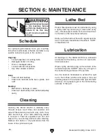
3. insert the tapered end of the center into
the spindle, and push it in with a quick, firm
motion, as shown in
figure 22.
headstock Center
Removing the Headstock center
1. disCoNNeCt lathe From poWer!
2. hold a clean rag under the spindle or wear a
glove to catch the center when you remove
it.
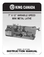
3. insert the knockout tool through the outbound
end of the spindle and firmly tap the back of
the center, catching it as it falls, as shown in
figure 23.
figure 23. removing the headstock center.
Knockout tool
figure 22. installing center into the headstock
spindle.
4. make sure the center is securely installed by
attempting to pull it out by hand—a properly
installed center will not pull out easily.
Always operate the lathe with the tool
rest assembly firmly locked in position.
Otherwise, serious personal injury may
occur by the tool being pulled from the
operator's hands.
Summary of Contents for G0733
Page 52: ......

