-30-
Model G0726 (Mfg. Since 7/11)
X- & Y-Axis Power Feeds
Graduated Dial Increments
Resolution
Each Mark ................................................. 0.001"
One Revolution ..........................................0.200"
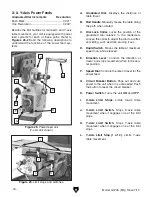
Besides the ball handles for manual X- and Y-axis
table movement, your mill is equipped with power
feed systems for each of these paths. Refer to
Figures 28–29 and the following descriptions to
understand the functions of the power feed sys-
tems.
A. Graduated Dial. Displays the distance of
table travel.
B. Ball Handle. Manually moves the table along
the path when rotated.
C. Dial Lock Collar. Locks the position of the
graduated dial relative to the leadscrew.
Loosen this collar to adjust the dial to a differ-
ent setting, such as when zeroing it out.
D. Rapid Switch. Moves the table at maximum
speed only while pressed.
E. Direction Lever: Controls the direction of
travel, and stops movement when in the cen-
ter position.
F. Speed Dial: Controls the rate of travel for the
power feed.
G. Circuit Breaker Button. Pops out and cuts
power to the unit when it is overloaded. Push
the button to reset the circuit breaker.
H. Power Switch. Turns the unit ON and OFF.
I. X-Axis Limit Stops. Limits X-axis table
movement.
J. X-Axis Limit Switch. Stops X-axis table
movement when it engages one of the limit
stops.
K. Y-Axis Limit Switch. Stops Y-axis table
movement when it engages one of the limit
stops.
L. Y-Axis Limit Stop (1 of 2). Limits Y-axis
table movement.
Figure 28. Power feed unit
(Y-axis unit shown).
A
B
C
G
F
E
D
H
Figure 29. Limit stops and switches.
J
I
L
K


