


-4-
Model G0701 (Mfd. Since 9/17)
Controls &
Components
To reduce your risk of
serious injury, read this
entire manual BEFORE
using machine.
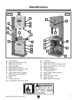
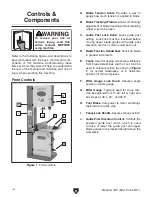
Refer to the following figures and descriptions to
become familiar with the basic controls and com-
ponents of this machine. Understanding these
items and how they work will help you understand
the rest of the manual and minimize your risk of
injury when operating this machine.
A. Blade Tension Scale: Provides a way to
gauge how much tension is applied to blade.
B. Blade Tracking Window: Allows monitoring/
adjustment of blade tracking without requiring
wheel cover to be open.
C. Guide Post Lock Knob: Locks guide post
setting. Lock knob must be loosened before
moving upper blade guides with guide post
elevation control, or motor could burn out.
D. Blade Tension Handwheel: Tensions blade
in gradual increments.
E. Fence: Used for ripping or resawing. Distance
from blade determines width of cut. Can be
used in vertical position (as shown in
Figure
1) for normal workpieces, or in horizontal
position for thin workpieces.
F. Miter Gauge Lock Knob: Secures angle
position of miter gauge.
G. Miter Gauge: Typically used for cross cuts.
Can be adjusted from 0°–60° left or right, and
has stops at 45°L, 90°, and 45°R.
H. Foot Brake: Cuts power to motor and brings
the blade to a quick stop.
I. Fence Lock Handle: Secures fence position.
J. Guide Post Elevation Control: Controls the
powered guide post motor, which is used
to raise or lower the guide post and upper
blade guides to the desired height above the
workpiece.
Front Controls
Figure 1. Front controls.
B
D
A
C
E
J
F
G
H
I