


-28-
Model G0701 (Mfd. Since 9/17)
Adjusting Blade
Guide Bearings
When properly adjusted to the blade, the upper
and lower blade guide bearings provide side-to-
side support that keeps the blade straight while
cutting.
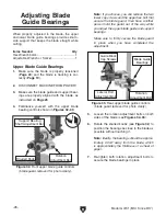
Figure 32. Front upper blade guide controls
(blade guard removed for photo clarity).
Rotation
Adjustment Bolt
Support Bearing
Shaft Adjustment Bolt
Knurled Knob
Figure 33. Rear upper blade guide controls
(blade guard removed for photo clarity).
Guide Block
Cap Screws
Blade Guide
Bearings
Rotation
Adjustment Bolt
Lateral Rod
Adjustment Bolt
Note: If you choose, you can remove the two
lower cap screws and the upper hex bolt that
secure the blade guard, then have another
person hold the guard out of the way while
you adjust the upper blade guide and support
bearings.
Make sure to firmly secure the blade guard
in place when you have completed the
adjustment.
5. Loosen the rotation adjustment bolts on both
sides of the blade (see
Figures 32–33).
6. Rotate the knurled knobs (see Figure 32) to
position the bearings as close to the blade as
possible without touching it.
Note: Ideally, the bearings should be approx-
imately 0.004" away from the blade, which
is approximately the thickness of a sheet of
paper.
7. Re-tighten both rotation adjustment bolts to
secure the blade bearings in place.
Upper Blade Guide Bearings
1. Make sure the blade is properly tensioned
(
Page 24) and the blade is tracking is cor-
rectly (
Page 19).
2. DISCONNECT MACHINE FROM POWER!
3. Make sure the blade guide and support bear-
ings are properly aligned with the blade, as
instructed on
Page 25.
4. Familiarize yourself with the upper blade
bearing controls shown in
Figures 32–33.
Items Needed
Qty
Hex Wrench 5mm .............................................. 1
Adjustable Wrench or Socket ............................ 1