


Model G0701 (Mfd. Since 9/17)
-21-
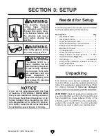
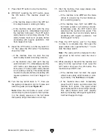
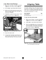
3. Loosen the table tilt lock handle, then use the
table tilt handwheel to raise the table (see
Figure 17).
Figure 17. Table tilted up.
Tilt Lock Lever
Tilt Handwheel
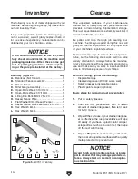
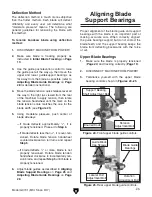
Figure 18. Positive stop bolt and jam nut.
Positive Stop
Bolt & Jam Nut
4. Open both wheel covers, use a 17mm wrench
to loosen the positive stop jam nut shown in
Figure 18, then lower the positive stop bolt
so that it will not interfere with the table tilt in
the following steps.
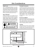
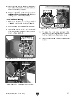
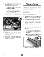
5. Lower the table and place a machinist's
square flat on the table and against the side
of the blade, as illustrated in
Figure 19.
Figure 19. Squaring table to the blade.
6. Use the table tilt handwheel to adjust the
table square to the blade, then move the tilt
lock lever to the right to secure the setting.
7. Adjust the positive stop bolt up until it just
touches the table, then re-tighten the jam nut
to hold it in place.
8. Re-check the table to make sure it is square
to the blade. If necessary, repeat this proce-
dure until you are satisfied.
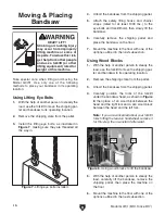
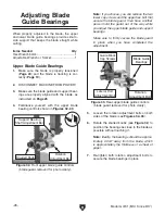
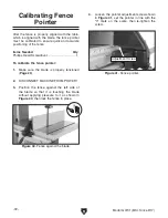
9. Loosen the screw on the table tilt scale point-
er, but do not remove it (see
Figure 20).
Figure 20. Table tilt scale pointer.
Scale
Pointer
10. Align the pointer tip with the zero on the
scale, then re-tighten the screw.
11. Close and secure both wheel covers before
beginning operation.