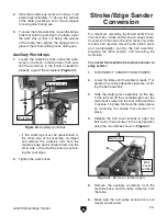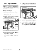
g0679 stroke/Edge sander
-19-
17
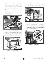
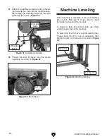
. attach the platen press rail assembly to the
left and right uprights with the (4)
1
⁄
4
-20 x
1
⁄
2
"
cap screws, as shown in
figure 27
.
20
. attach the table stop with (2)
5
⁄
16
-18 x
1
⁄
2
flange bolts (
figure 30
).
19
. slide the larger handwheel on the elevation
control shaft and the smaller handwheel
on the belt tension shaft, then secure each
by tightening the set screws and lock nuts
(
figure 29
).
18
. insert the platen press assembly and the
platen press counterweight into the platen
press slide, then tighten the lock lever and
cap screw, as shown in
figure 28
.
figure 27.
Platen press rail assembly.
figure 30.
Table stop attachment.
figure 29.
Handwheel Attachment.
figure 28.
Platen press and counterweight.
upright
rail assembly
platen press
Counterweight
platen press slide
table Elevation
handwheel
Belt tension
handwheel
table stop
Flange Bolt
Cap screws
Summary of Contents for G0679
Page 15: ...G0679 Stroke Edge Sander 13 Hardware Recognition Chart...
Page 42: ...40 G0679 Stroke Edge Sander Main Breakdown SECTION 9 PARTS...
Page 44: ...42 G0679 Stroke Edge Sander Belt Idler Wheel Assembly Breakdown...
Page 47: ...G0679 Stroke Edge Sander 45 Right Upright Assembly Breakdown...
Page 49: ...G0679 Stroke Edge Sander 47 Left Upright Assembly Breakdown...


