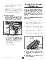
-18-
g0679 stroke/Edge sander
13
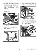
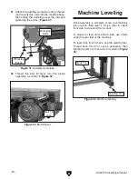
. place the switch boom into the switch boom
socket and secure with the lock knob, as
shown in
figure 23
.
14
. slide the two table rails into the table bear-
ing assemblies on both sides of the frame
(
figure 24
).
15
. With the help of an assistant, place the table
over the table rails and secure it with the (4)
5
⁄
16
-18 x
3
⁄
4
" cap screws and
5
⁄
16
" flat washers
(
figure 25
).
16
. attach the rear cover to the left and right
uprights with the (6)
1
⁄
4
-20 x
1
⁄
2
" phillips head
screws, as shown in
figure 26
.
figure 23.
Switch boom.
switch Boom
switch Boom
socket
lock
Knob
figure 24.
Table rails.
table rail
table Bearing
assembly
figure 25.
Table mounting.
table
table rail
Cap screw
Cap screw
figure 26.
Rear cover.
upright
rear Cover
phillips head screws
Summary of Contents for G0679
Page 15: ...G0679 Stroke Edge Sander 13 Hardware Recognition Chart...
Page 42: ...40 G0679 Stroke Edge Sander Main Breakdown SECTION 9 PARTS...
Page 44: ...42 G0679 Stroke Edge Sander Belt Idler Wheel Assembly Breakdown...
Page 47: ...G0679 Stroke Edge Sander 45 Right Upright Assembly Breakdown...
Page 49: ...G0679 Stroke Edge Sander 47 Left Upright Assembly Breakdown...


