background image

G0592 Metal Cutting Bandsaw

-7-

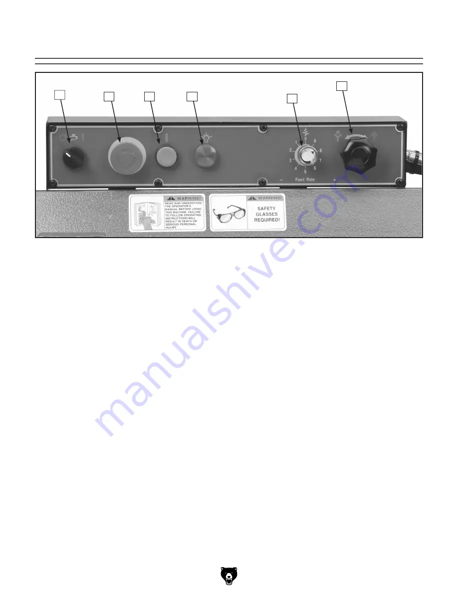
Control Panel

A.  Coolant  Pump  Switch:

  Turns  the  coolant 

pump 

ON.

B.  EMERGENCY


STOP/OFF Button:

 Interrupts 

power  to  the  system  and  turns  the  motor 

OFF

.  Twist the button until it pops out to re-

energize  the  system.  Also  works  as  a  stan-
dard OFF button. 


Note:


The bandsaw has an automatic shut-

off (limit switch) that turns the machine 

OFF


at the completion of the cutting arc.

C.  START  Button:

  Turns  the  motor 

ON 

and 

activates moving parts.


D.  Power Light:

 When lit, indicates that system 

is  energized  and  machine  is  ready  to  oper-
ate.

E.


Feed Rate Dial: 

Fine tunes the feed rate by 

controlling the hydraulic valve. Range is from 
1 being slowest to 9 being fastest.

F.  Feed Control Knob:

 Turning the knob to the 

left lowers the bow at the feed rate you have 
set.  Turning  the  knob  to  the  right  locks  the 
bow in position.

Figure 2.

 G0592 control panel.

A

B

C

D

E

F

Summary of Contents for G0592

Page 1: ...utting Bandsaw OWNER S MANUAL COPYRIGHT MAY 2006 BY GRIZZLY INDUSTRIAL INC WARNING NO PORTION OF THIS MANUAL MAY BE REPRODUCED IN ANY SHAPE OR FORM WITHOUT THE WRITTEN APPROVAL OF GRIZZLY INDUSTRIAL INC PC7789 PRINTED IN TAIWAN ...

Page 2: ... ...

Page 3: ...t Up Safety 12 Items Needed for Set Up 12 Unpacking 12 Inventory 13 Hardware Recognition Chart 14 Clean Up 15 Site Considerations 15 Moving Placing Base Unit 16 Mounting to Shop Floor 16 Shipping Bracket 17 Workstop 17 Chip Trays Splash Guard 18 Feed Stop 18 Recommended Adjustments 19 Test Run 19 SECTION 4 OPERATIONS 20 Operation Safety 20 Vise 20 Cutting Angle 22 Blade Selection 23 Blade Speed 23...

Page 4: ...l G0592 220V Wiring Diagram 39 Base Parts Breakdown 40 Base Parts List 41 Swivel Base Parts Breakdown 42 Swivel Base Parts List 43 Vise Parts Breakdown 44 Vise Parts List 45 Bow Parts Breakdown 46 Bow Parts List 47 Blade Tension Motor Parts Breakdown 48 Blade Tension Motor Parts List 49 Blade Guides Parts Breakdown 50 Blade Guides Parts List 51 Electrical Parts Breakdown 52 Electrical Parts List 5...

Page 5: ... set forth in this manual you can expect years of trouble free enjoyable operation and proof of Grizzly s com mitment to customer satisfaction We are pleased to provide this manual with the Model G0592 It was written to guide you through assembly review safety considerations and cover general operating procedures It repre sents our effort to produce the best documenta tion possible The specificati...

Page 6: ...ent Machine Weight 967 lbs Length Width Height 79 x 36 x 49 in Electrical Switch On Off Located on Saw Bow Switch Voltage 220V Cord Length 6 ft Cord Gauge 14 gauge Recommended Breaker Size 20 amp Plug Yes Motors Main Type TEFC Capacitor Start Induction Horsepower 2 HP Voltage 220V Prewired 220V Phase Single Amps 15A Speed 1720 RPM Cycle 60 Hz Number Of Speeds 1 Power Transfer V Belt Drive Bearings...

Page 7: ...acity Rect Width At 60 8 in Max Capacity Rnd At 60 8 in Construction Table Construction Cast Iron Wheel Construction Upper Cast Iron Wheel Construction Lower Cast Iron Body Construction Formed Steel Base Construction Cast Iron Stand Construction Formed Steel Wheel Cover Construction Pre Formed Steel Paint Epoxy Other Blade Guides Upper Ball Bearing Blade Guides Lower Ball Bearing Coolant Capacity ...

Page 8: ... C Vise Handwheel D Coolant Pan E Work Stop F Rotational Degree Scale G Spray Gun H Electrical Enclosure I Speed Adjustment Knob J Control Panel K Blade Guide Scale L Blade Guide Knob M Coolant Valve Controls N Bow O Speed Blade Selection Chart P Blade Guides Identification A C B D E F G H I J K L M O P N ...

Page 9: ...hat turns the machine OFF at the completion of the cutting arc C START Button Turns the motor ON and activates moving parts D Power Light When lit indicates that system is energized and machine is ready to oper ate E Feed Rate Dial Fine tunes the feed rate by controlling the hydraulic valve Range is from 1 being slowest to 9 being fastest F Feed Control Knob Turning the knob to the left lowers the...

Page 10: ...n and can cause cancer and severe respiratory illnesses For Your Own Safety Read Instruction Manual Before Operating this Machine The purpose of safety symbols is to attract your attention to possible hazardous conditions This manual uses a series of symbols and signal words which are intended to convey the level of importance of the safety messages The progression of symbols is described below Re...

Page 11: ...sories 16 MAKE SURE GUARDS ARE IN PLACE AND WORK CORRECTLY BEFORE USING MACHINERY Safety Instructions for Machinery 17 REMOVE ADJUSTING KEYS AND WRENCHES Make a habit of checking for keys and adjusting wrenches before turn ing machinery ON 18 CHECK FOR DAMAGED PARTS BEFORE USING MACHINERY Check for binding and alignment of parts broken parts part mounting loose bolts and any other conditions that ...

Page 12: ...r badly worn blade Inspect blades for cracks and missing teeth before each use 2 HAND PLACEMENT Never position fin gers or thumbs in line with the cut Hands could be crushed in vise or by falling machine components or cut by the blade 3 ENTANGLEMENT HAZARDS Do not operate this bandsaw without blade guard in place Otherwise loose clothing jewelry long hair and work gloves can be drawn into working ...

Page 13: ...ing circuit with one of higher amper age without consulting a qualified electrician to ensure compliance with wiring codes If you are unsure about the wiring codes in your area or you plan to connect your machine to a shared circuit consult a qualified electrician 220V Circuit 20 Amps Plug Receptacle Type Recommended Plug Receptacle NEMA L6 20 SECTION 2 CIRCUIT REQUIREMENTS Electrocution or fire co...

Page 14: ... cess This machine presents serious injury hazards to untrained users Read through this entire manu al to become familiar with the controls and opera tions before starting the machine Unpacking Set Up Safety SECTION 3 SET UP The following items are needed to complete the set up process but are not included with your machine Description Qty Safety Glasses for each person 1 Solvent Cleaner 1 Shop To...

Page 15: ... Feet 4 H Model G0592 Bandsaw not shown 1 In the event that any nonproprietary parts are missing e g a nut or a washer we would be glad to replace them or for the sake of expedi ency replacements can be obtained at your local hardware store Figure 4 G0592 loose inventory A B C D E F G NOTICE Some hardware fasteners on the inventory list may arrive pre installed on the machine Check these locations...

Page 16: ... 14 G0592 Metal Cutting Bandsaw Hardware Recognition Chart ...

Page 17: ...ion during ship ment Remove this protective coating with a sol vent cleaner or citrus based degreaser such as Grizzly s G7895 Degreaser To clean thoroughly some parts may need to be removed For opti mum performance from your machine make sure you clean all moving parts or sliding contact surfaces that are coated Avoid chlo rine based solvents such as acetone or brake parts cleaner as they will dam...

Page 18: ...erally you can either bolt your machine to the floor or mount it on machine mounts It will be necessary to level your machine after mount ing If you choose to set your machine on the floor four M12 1 75 x 50 leveling bolts have been included Bolting to Concrete Floors Lag shield anchors with lag bolts Figure 7 and anchor studs are two popular methods for anchoring an object to a concrete floor Mou...

Page 19: ...ch 2 Remove the two lower cap screws with a 5mm hex wrench Figure 10 Workstop The workstop on the Model G0592 has three main parts including the workstop rod arm and work stop The workstop is easy to adjust and can be set up on either side of the vise To install the workstop 1 Slide the workstop rod in the hole in the base of the vise and tighten the set screw 2 Slide the arm onto the workstop rod...

Page 20: ...ean up Figure 12 Splash tray installation Figure 13 Feed stop Jam Nut Feed Stop Feed Stop Figure 11 Chip tray set up Upper Chip Tray Lower Chip Tray The splash tray fits over the lip of the base as illustrated in Figure 12 Depending on how the G0592 was shipped it may be necessary to adjust the feed stop before the test run The blade should not make contact with any part of the vise assembly To ad...

Page 21: ...on safety glasses and secure loose clothing or long hair 4 Connect the bandsaw to power 5 Raise the bandsaw and close the feed con trol knob to keep the saw in place Projectiles thrown from the machine could cause serious eye injury Wear safety glasses during assembly and operation Test Run 6 Start the bandsaw while keeping your finger near the EMERGENCY STOP OFF button Figure 14 at all times duri...

Page 22: ...NGLY RECOMMEND that you read books trade magazines and get formal training before beginning any projects Regardless of the content in this section Grizzly Industrial will not be held liable for accidents caused by lack of training The vise on the Model G0592 can be positioned for cutting on both sides of the vise It also has a ratcheting type leadscrew that allows for fast jaw adjustments To chang...

Page 23: ...change the vise jaw gap 1 Use the handwheel to relieve any pressure on the vise jaw 2 Flip the latch up to disengage it from the leadscrew see Figure 17 3 Pull or push the jaw in the desired direction 4 Engage the lever with the leadscrew and fin ish tightening the jaw with the handwheel Note Figure 18 shows the proper methods for holding different workpiece shapes Always turn the saw OFF and allo...

Page 24: ...highest position and lock in place 2 Flip the stop out as shown in Figure 19 Figure 20 Swivel lock lever 3 Loosen the swivel lock lever Figure 20 rotate the turret to the desired angle then re tighten the swivel lock lever Figure 19 Stop Stop 4 To return to 0 flip the stop up Note Adjust the set screw on the stop to calibrate the scale to the stop Swivel Lock Lever Stop Set Screw ...

Page 25: ...8 The chart shown in Figure 21 is a reproduction of the chart you will find on the blade cover of your G0592 Use it as a rough guideline Blade Speed To change blade speeds 1 Turn the bandsaw ON and allow it to come up to speed 2 Turn the speed adjustment knob Figure 23 clockwise to decrease blade speed and counterclockwise to increase blade speed NOTICE Only change speeds while the motor is run ni...

Page 26: ...om insuffi cient feed pressure This will dull your blade rapidly The best cut and feed rate will give you evenly shaped spiraled curls with very little color change if any at all Feed Rate Figure 23 Feed rate dial shown with guard removed Feed Rate Dial Material Alloy ASTM Number Ft Min Mtrs Min Copper 173 932 314 96 Alloys 330 365 284 87 623 624 264 81 230 260 272 244 74 280 264 632 655 244 74 10...

Page 27: ...h Coolant System FIRE HAZARD DO NOT cut magnesium when using oil water solutions as a cutting fluid Always use a cutting fluid intend ed for magnesium The water in the solution will cause a magnesium chip fire This bandsaw has a built in coolant system that extends the life of your bandsaw blades by lower ing the temperature of the blade and workpiece It also has a convenient spray gun to help you...

Page 28: ...witch ON before making your cut NOTICE Keep the tray chip screen clear so coolant can recycle to the pump reservoir NEVER operate the pump with the reservoir below the low mark or you will over heat the pump and void your warranty Figure 29 Spray gun 6 Monitor the coolant level frequently to keep the system working properly DO NOT let coolant level fall out of view on the sight glass see Figure 28...

Page 29: ...minimize side to side blade movement Use coolant when possible to increase blade life Operation Tips NOTICE Loosen blade tension at the end of each day to prolong blade life While simple in concept and function many issues must be taken into account to find and use the correct cutting fluid Always follow all product warnings and contact the fluid manufacturer for unanswered questions Use the selec...

Page 30: ... 8 Variable Pitch H1149 132 x 1 x 032 6 10 Variable Pitch H1150 132 x 1 x 032 8 12 Variable Pitch H1151 132 x 1 x 032 10 14 Variable Pitch H5405 Lenox Lube Tube Lenox Lube Tube is a stick lubricant designed to prevent heat buildup Apply it directly to the blade to improve overall blade life and productiv ity Can be used on ferrous and non ferrous met als Biodegradeable non toxic and non staining 1...

Page 31: ...Radio Headset Earmuffs Protect yourself comfortably with a pair of cush ioned earmuffs Especially important if you or employees operate for hours at a time H1302 H4977 H4979 G9256 6 Dial Caliper G9257 8 Dial Caliper G9258 12 Dial Caliper These traditional dial calipers are accurate to 0 001 and can measure outside surfaces inside surfaces and heights depths Features stainless steel shock resistant...

Page 32: ...e gear box oil every four months if being used daily Schedule Before applying lubricant to any area wipe the area clean to avoid contamination Lubricate the vise leadscrew and the grease fittings at the pivot point shown in Figure 38 with general purpose grease All bearings on the Model G0592 are lubricated and sealed for the life of the bearing No further attention is needed until it is time to r...

Page 33: ...ch the halfway point in the sight glass see Figure 39 7 Tighten the fill plug connect the machine to power and run the saw for a minute or two then reinspect the oil level Add more oil if needed to maintain level at the halfway mark in the sight glass Figure 40 Vise leadscrew lubrication area Leadscrew 8 Lubricate the leadscrew as needed with general purpose grease Apply a thin layer all along the...

Page 34: ...ken wires or disconnected corroded connections and repair replace as necessary 9 Test repair replace Machine stalls or is under powered 1 Wrong blade for the workpiece material 2 Wrong workpiece material 3 Feed rate cutting speed too fast for task 4 Blade is slipping on wheels 5 Low power supply voltage 6 Motor bearings are at fault 7 Plug receptacle is at fault 8 Motor connection is wired incor r...

Page 35: ...pots welds or scale is on the material 5 The blade is twisted 6 The blade is slipping on the wheels 1 Refer to Changing Blade Speed on Page 23 and adjust as required 2 Refer to Blade Selection on Page 23 and adjust as required 3 Refer to Feed Rate on Page 24 and adjust as required 4 Increase the feed pressure and reduce the cutting speed 5 Replace the blade 6 Refer to Blade Tension on Page 35 and ...

Page 36: ...e and blade Tension Handle 4 Remove the blade guard and wire wheel from the front of the bandsaw as shown in Figure 42 Figure 42 Removing front blade guard Front Blade Guard 5 Loosen the blade tension handle in Figure 41 and slip the blade off of the wheels 6 Install the new blade through both blade guide bearings as shown in Figure 43 and around the bottom wheel CUTTING HAZARD Blades are sharp We...

Page 37: ...re 45 until the blade is tracking properly Figure 45 Blade tension guide Blade Tension Guide NOTICE Loosen blade tension at the end of each day to prolong blade life To tension the blade on the bandsaw 1 Turn the blade tension handle clockwise to tension the blade 2 Use the graduated scale on the blade tension indicator Figure 45 to determine blade ten sion in PSI For carbon blades the blade tensi...

Page 38: ...t loosen the two cap screws shown in Figure 46 Lower the blade guide until the back of the blade makes light con tact with the backing bearing Then tighten the two cap screws Figure 46 Blade guide adjustments Hex Nut Backing Bearing Eccentric Bushing Carbide Blade Guide Guide Bearings 6 Loosen the set screw in Figure 47 to allow the eccentric bushing to turn 7 Turn the hex nut on the eccentric sha...

Page 39: ...G0592 Metal Cutting Bandsaw 37 Electrical Components Figure 48 Limit switch Figure 51 Pump motor wiring Figure 50 Control panel wiring Figure 49 Junction box ...

Page 40: ... 38 G0592 Metal Cutting Bandsaw Electrical Components Figure 52 G0592 Contactor relay electrical box Contactor Relay Transformer Terminal Block ...

Page 41: ...G0592 Metal Cutting Bandsaw 39 Model G0592 220V Wiring Diagram ...

Page 42: ... 40 G0592 Metal Cutting Bandsaw Base Parts Breakdown ...

Page 43: ...COOLANT RESERVOIR 26 P0592026 CHIP TRAY 3 PS09M PHLP HD SCR M5 8 X 10 27 P0592027 LOCATING FOOT RIGHT 3 1 PW02M FLAT WASHER 5MM 29 P0592029 SPRAY ASSEMBLY 4 P0592004 ACRYLIC PLATE 29 1 P0592029 1 HOSE 7 PB18M HEX BOLT M6 1 X 15 29 2 P0592029 2 HOSE CLAMP 8 PW03M FLAT WASHER 6MM 29 3 P0592029 3 HOSE 9 P0592009 SHIPPING BRACKET 29 4 P0592029 4 SPRAY GUN 10 PW01M FLAT WASHER 8MM 29 5 P0592029 5 MICRO...

Page 44: ... 42 G0592 Metal Cutting Bandsaw Swivel Base Parts Breakdown ...

Page 45: ...SCREW M6 1 X 10 114 PW06M FLAT WASHER 12MM 147 P05920147 SWITCH BRACKET 115 P05920115 HANDLE 148 PW01M FLAT WASHER 8MM 116 P05920116 SCREW ROD 149 PB17M HEX BOLT M8 1 25 X 10 117 P05920117 HUB 150 PN09M HEX NUT M12 1 75 118 P05920118 PIVOT BOLT 151 PB33M HEX BOLT M12 1 75 X 50 119 PSB84M CAP SCREW M10 1 5 X 35 152 P05920152 ANGLE MARGIN 120 PN09M HEX NUT M12 1 75 153 PSB14M CAP SCREW M8 1 25 X 20 ...

Page 46: ... 44 G0592 Metal Cutting Bandsaw Vise Parts Breakdown ...

Page 47: ...0210 UPPER CHIP TRAY 235 PSB47M CAP SCREW M10 1 5 X 40 211 PSB72M CAP SCREW M10 1 5 X 30 236 P05920236 VISE JAW BRACKET REAR 212 P05920212 FIXED BLOCK 237 PLW05M LOCK WASHER 12MM 213 P05920213 BUSHING 238 PSB131M CAP SCREW M12 1 75 X 45 214 P05920214 KNOB M10 1 5 X 40 239 PSB45M CAP SCREW M8 1 25 X 45 215 P05920215 HANDWHEEL 240 PLW04M LOCK WASHER 8MM 216 PSS01M SET SCREW M6 1 X 10 241 P05920241 S...

Page 48: ... 46 G0592 Metal Cutting Bandsaw Bow Parts Breakdown ...

Page 49: ...0423 GEAR BOX ASSEMBLY 406 1 P05920406 1 SAFETY GLASSES LABEL 424 P05920424 SPLASH BOARD 407 P05920407 HANDLE 425 P05920425 SPECIAL WASHER 408 PN08 HEX NUT 3 8 16 426 PSB04M CAP SCREW M6 1 X 10 409 P05920409 RIVET 427 P05920427 3 WAY VALVE ASSY 410 P05920410 LOOSEN TIGHTEN LABEL 427 1 P05920427 1 HOSE CLAMP 411 P05920411 BLADE GUARD LABEL 427 2 P05920427 2 STRAIGHT CONNECTOR 412 P05920412 BOW FRAM...

Page 50: ... 48 G0592 Metal Cutting Bandsaw Blade Tension Motor Parts Breakdown ...

Page 51: ...6 PS52M PHLP HD SCR M4 7 X 20 465 PW02M FLAT WASHER 5MM 497 P05920497 SCALE 466 P05920466 COVER 498 PW05M FLAT WASHER 4MM 467 PS45M PHLP HD SCR M5 8 X 5 499 PS38M PHLP HD SCR M4 7 X 10 469 P05920469 SPEED LABEL 500 P05920500 DISC SPRING 470 P05920470 WASHER RING 501 PSB12M CAP SCREW M8 1 25 X 40 471 P05920471 MOTOR BRACKET 502 PLW04M LOCK WASHER 8MM 472 PW03M FLAT WASHER 6MM 503 P05920503 GIB 473 ...

Page 52: ... 50 G0592 Metal Cutting Bandsaw Blade Guides Parts Breakdown ...

Page 53: ...556 P0592556 VALVE ASSY 582 PS09M PHLP HD SCR M5 8 X 10 556 1 P0592556 1 COPPER TUBE 583 PW02M FLAT WASHER 5MM 556 2 P0592556 2 VALVE 586 P0592586 BLADE ADJUSTER REAR 556 3 P0592556 3 STRAIGHT CONNECTOR 587 PSS07M SET SCREW M5 8 X 5 556 4 P0592556 4 HOSE CLAMP 588 P0592588 COLLAR 556 5 P0592556 5 NET TUBE 1 4 X 143CM 589 1 P0592589 1 BRUSH SHAFT 556 6 P0592556 6 NET TUBE 1 4 X 63CM 589 2 PS81M PHL...

Page 54: ... 52 G0592 Metal Cutting Bandsaw Electrical Parts Breakdown ...

Page 55: ...CONTROL PLATE 713 18 P0592713 18 STRAIN RELIEF 712 PS08M PHLP HD SCR M5 8 X 12 713 19 P0592713 19 PUMP WIRE HARNESS 713 P05920713 CONTROL BOX 713 20 P0592713 20 MOTOR WIRE HARNESS 713 1 P0592713 1 PUMP RELAY 713 21 P0592713 21 STRAIN RELIEF 713 2 P0592713 2 CONTACTOR CN 18 713 22 P0592713 22 CNTRL PANEL WIRE HARNESS 713 3 P0592713 3 ON BUTTON 713 23 P0592713 23 LIMIT SWITCH WIRE HARNESS 713 4 P059...

Page 56: ...all be tried in the State of Washington County of Whatcom We shall in no event be liable for death injuries to persons or property or for incidental contingent special or consequential damages arising from the use of our products To take advantage of this warranty contact us by mail or phone and give us all the details We will then issue you a Return Number which must be clearly posted on the outs...

Page 57: ... ...

Page 58: ... ...

Page 59: ......

Page 60: ... ...

Reviews: