background image

-6-

Model G0555LX


(Mfd. Since 1/14)

ELECTRICAL EQUIPMENT INJURY RISKS. 

You can be shocked, burned, or killed by touching 

live electrical components or improperly grounded 

machinery. To reduce this risk, only allow qualified 

service  personnel  to  do  electrical  installation  or 

repair work, and always disconnect power before 

accessing or exposing electrical equipment.

DISCONNECT POWER FIRST.  Always  discon-

nect  machine  from  power  supply  BEFORE  mak-

ing  adjustments,  changing  tooling,  or  servicing 

machine.  This  prevents  an  injury  risk  from  unin-

tended  startup  or  contact  with  live  electrical  com-

ponents.

EYE PROTECTION. Always wear ANSI-approved 

safety glasses or a face shield when operating or 

observing  machinery  to  reduce  the  risk  of  eye 

injury or blindness from flying particles. Everyday 

eyeglasses are NOT approved safety glasses.

OWNER’S MANUAL. Read and understand this 

owner’s manual BEFORE using machine. 

TRAINED OPERATORS ONLY. Untrained oper-

ators  have  a  higher  risk  of  being  hurt  or  killed. 

Only  allow  trained/supervised  people  to  use  this 

machine.  When  machine  is  not  being  used,  dis-

connect  power,  remove  switch  keys,  or  lock-out 

machine to prevent unauthorized use—especially 

around children. Make your workshop kid proof!

DANGEROUS ENVIRONMENTS. Do  not  use 

machinery in areas that are wet, cluttered, or have 

poor lighting. Operating machinery in these areas 

greatly increases the risk of accidents and injury.

MENTAL ALERTNESS REQUIRED. Full mental 

alertness is required for safe operation of machin-

ery. Never operate under the influence of drugs or 

alcohol, when tired, or when distracted.

For Your Own Safety, Read Instruction 

Manual Before Operating This Machine

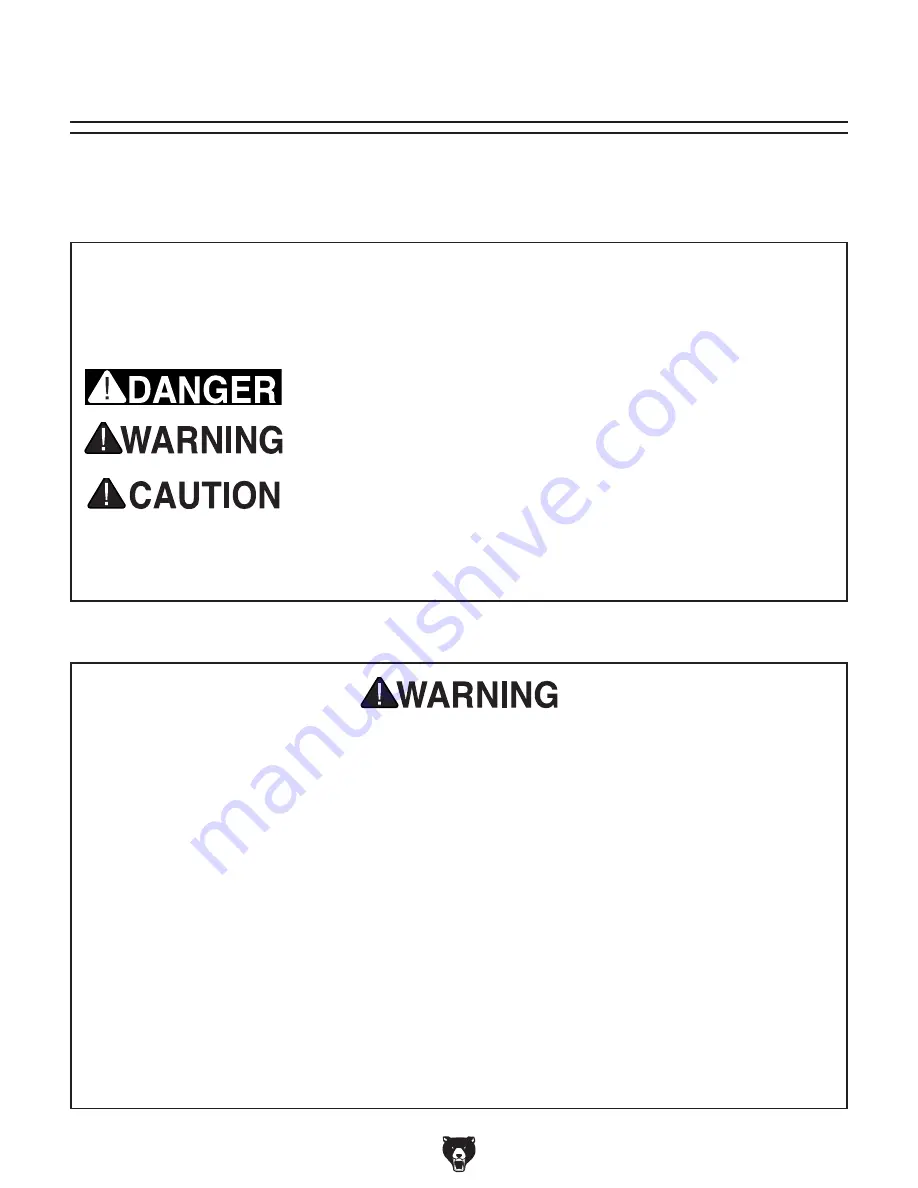
The purpose of safety symbols is to attract your attention to possible hazardous conditions. 

This manual uses a series of symbols and signal words intended to convey the level of impor-

tance of the safety messages. The progression of symbols is described below. Remember that 

safety messages by themselves do not eliminate danger and are not a substitute for proper 

accident prevention measures. Always use common sense and good judgment.

Indicates a potentially hazardous situation which, if not avoided, 
MAY result in minor or moderate injury. It may also be used to alert 
against unsafe practices.

Indicates a potentially hazardous situation which, if not avoided, 
COULD result in death or serious injury.

Indicates an imminently hazardous situation which, if not avoided, 
WILL result in death or serious injury.

Alerts the user to useful information about proper operation of the 
machine to avoid machine damage.

NOTICE

Safety Instructions for Machinery

SECTION 1: SAFETY

Summary of Contents for G0555LX

Page 1: ...ARNING NO PORTION OF THIS MANUAL MAY BE REPRODUCED IN ANY SHAPE OR FORM WITHOUT THE WRITTEN APPROVAL OF GRIZZLY INDUSTRIAL INC KN14662 PRINTED IN TAIWAN MODEL G0555LX 14 DELUXE BANDSAW OWNER S MANUAL For models manufactured since 1 14 Keep for Future Reference 177335 V3 08 22 ...

Page 2: ...ng grinding tool integrity and the usage of personal protective equipment The manufacturer will not be held liable for injury or property damage from negligence improper training machine modifications or misuse Some dust created by power sanding sawing grinding drilling and other construction activities contains chemicals known to the State of California to cause cancer birth defects or other repr...

Page 3: ... 31 Calibrating Miter Gauge 31 SECTION 4 OPERATIONS 32 Operation Overview 32 Disabling Locking Switch 33 Workpiece Inspection 34 Guide Post 34 Table Tilt 35 Blade Speed 35 Blade Information 36 Changing Blade 38 Installing 1 4 Eccentrics 39 Ripping 40 Crosscutting 41 Resawing 41 Cutting Curves 42 Stacked Cuts 42 SECTION 5 ACCESSORIES 43 SECTION 6 MAINTENANCE 44 Schedule 44 Lubrication 44 Cleaning P...

Page 4: ...e between the manual and machine leaves you confused or unsure about something check our website for an updated version We post current manuals and manual updates for free on our web site at www grizzly com Alternatively you can call our Technical Support for help Before calling make sure you write down the manufacture date and serial number from the machine ID label see below This information is ...

Page 5: ...er Blade Tension Scale Blade Tracking Knob Guide Post Control Knob Guide Post Control Knob Upper Blade Guide Assembly Fence Lock Handle For Your Own Safety Read Instruction Manual Before Operating Saw a Wear eye protection b Do not remove jammed cutoff pieces until blade has stopped c Maintain proper adjustment of blade tension blade guides and thrust bearings d Adjust upper guide to just clear wo...

Page 6: ...ype Cardboard Box Content Stand Weight 42 lbs Length x Width x Height 28 1 2 x 23 x 9 in Electrical Power Requirement 110V or 220V Single Phase 60 Hz Prewired Voltage 110V Full Load Current Rating 11A at 110V 5 5A at 220V Minimum Circuit Size 15A at 110V 15A at 220V Connection Type Cord Plug Power Cord Included Yes Power Cord Length 6 ft Power Cord Gauge 16 AWG Plug Included Yes Included Plug Type...

Page 7: ...djustment Type Manual Floor to Table Height 43 in Fence Locking Position Front Fence is Adjustable for Blade Lead Yes Resaw Fence Attachment Included No Miter Gauge Included Yes Construction Materials Table Precision Ground Cast Iron Trunnion Aluminum Fence Deluxe Extruded Aluminum Base Stand Pre Formed Steel Frame Body Cast Iron Wheels Computer Balanced Cast Iron Tire Rubber Wheel Cover Pre Forme...

Page 8: ...id proof DANGEROUS ENVIRONMENTS Do not use machinery in areas that are wet cluttered or have poor lighting Operating machinery in these areas greatly increases the risk of accidents and injury MENTAL ALERTNESS REQUIRED Full mental alertness is required for safe operation of machin ery Never operate under the influence of drugs or alcohol when tired or when distracted For Your Own Safety Read Instr...

Page 9: ... moving parts or flying debris Make sure they are properly installed undamaged and working correctly BEFORE operating machine FORCING MACHINERY Do not force machine It will do the job safer and better at the rate for which it was designed NEVER STAND ON MACHINE Serious injury may occur if machine is tipped or if the cutting tool is unintentionally contacted STABLE MACHINE Unexpected movement dur i...

Page 10: ...s Always keep workpiece flat and firm against table fence when cutting to avoid loss of control If necessary use a jig or other work holding device WORKPIECE MATERIAL This machine is intended for cutting natural and man made wood products and laminate covered wood products This machine is NOT designed to cut metal glass stone tile etc HAND PLACEMENT Placing hands or fingers in line with blade duri...

Page 11: ...n and make sure it is connected to a power supply circuit that meets the specified circuit requirements For your own safety and protection of property consult an electrician if you are unsure about wiring practices or electrical codes in your area Note Circuit requirements in this manual apply to a dedicated circuit where only one machine will be running on the circuit at a time If machine will be...

Page 12: ...following size requirements Minimum Gauge Size 14 AWG Maximum Length Shorter is Better 50 ft Grounding Requirements This machine MUST be grounded In the event of certain malfunctions or breakdowns grounding reduces the risk of electric shock by providing a path of least resistance for electric current Figure 1 Typical 5 15 plug and receptacle Grounding Pin Neutral Hot 5 15 PLUG GROUNDED 5 15 RECEP...

Page 13: ... service personnel The voltage conversion procedure consists of rewiring the motor and installing the correct plug The nec essary wiring diagrams are provided in the Wiring section beginning on Page 55 for your reference IMPORTANT If the diagram on the motor con flicts with the diagrams in the Wiring section the motor may have changed since the manual was printed Use the diagram on the motor inste...

Page 14: ...Needed Cleaner Degreaser As Needed Level 1 Wrench or Socket 7 16 1 2 1 Ea Wrenches or Sockets 9 16 2 Disposable Gloves As Needed Square 1 Dust Hose 4 1 Hose Clamp 4 1 Needed for Setup The following items are needed but not included for the setup assembly of this machine This machine was carefully packaged for safe transport When unpacking separate all enclosed items from packaging materials and in...

Page 15: ...et 3 8 16 x 2 Stand 4 Carriage Bolts 5 16 18 x 5 8 Stand 8 Flange Nuts 5 16 18 Stand 8 Hex Nuts 3 8 16 Stand Feet 8 Flat Washer 3 8 Stand Feet 8 Open End Wrench 10 x 12mm 1 Hex Wrench 5mm 1 Switch Padlock w Keys 1 Eccentrics 1 4 2 Quick Release Lever 1 C J Figure 5 Main components inventory B K A NOTICE If you cannot find an item on this list care fully check around inside the machine and packagin...

Page 16: ... 14 Model G0555LX Mfd Since 1 14 Hardware Recognition Chart USE THIS CHART TO MATCH UP HARDWARE DURING THE INVENTORY AND ASSEMBLY PROCESS 5mm 5mm Flat Head Cap Screw ...

Page 17: ...ing gather the following Disposable rags Cleaner degreaser WD 40 works well Safety glasses disposable gloves Plastic paint scraper optional Basic steps for removing rust preventative 1 Put on safety glasses 2 Coat the rust preventative with a liberal amount of cleaner degreaser then let it soak for 5 10 minutes 3 Wipe off the surfaces If your cleaner degreas er is effective the rust preventative w...

Page 18: ...ironment The physical environment where the machine is operated is important for safe operation and lon gevity of machine components For best results operate this machine in a dry environment that is free from excessive moisture hazardous chemi cals airborne abrasives or extreme conditions Extreme conditions for this type of machinery are generally those where the ambient temperature range exceeds...

Page 19: ... be anchored to the floor If not required by any local codes fastening the machine to the floor is an optional step If you choose not to do this with your machine we rec ommend placing it on machine mounts as these provide an easy method for leveling and they have vibration absorbing pads Lag shield anchors with lag screws see below are a popular way to anchor machinery to a con crete floor becaus...

Page 20: ...feet are tight against the stand assembly so they will not move Figure 13 Leveling the stand 2 Attach the remaining stand side to the assem bly as shown in Figure 10 with 8 1 4 20 x 5 8 hex bolts 8 1 4 flat washers and 8 1 4 20 flange nuts Figure 10 Second stand side attached 3 Install the stand feet as shown in Figure 11 in the bottom of the stand assembly using a 3 8 16 x 2 stand foot 2 3 8 16 h...

Page 21: ... the blade then position the table so that the blade is in the center cut out 10 Rotate the table so that the table slot faces to the right then position the table trunnion on the bandsaw as shown in Figure 15 and secure it with 2 5 16 18 x 11 4 hex bolts and 2 5 16 lock washers 11 Tighten the trunnion lock knobs to secure the table 12 Re install the table insert and table pin as shown in Figure 1...

Page 22: ...ck Release Lever Upper Clutch 15 Pull the fence handle up slip the L brace over the back of the rear fence rail see Figure 19 and lower the fence onto the front fence rail as shown in Figure 20 14 Attach the front fence rail shown in Figure 18 with 2 1 4 20 x 3 4 hex bolts and 1 4 flat washers Figure 18 Installing front fence rail Front Fence Rail x 2 Figure 19 L Brace positioned over rear fence r...

Page 23: ...the bandsaw must be aligned for the blade to track correctly on the crown of the wheel Properly aligned wheels are parallel and coplanar see Figure 23 Improper blade tension and cutting practices can negatively affect blade tracking Familiarizing yourself with the ideas and conditions described in Figure 23 will help you recognize when your saws wheel alignment may need adjusted refer to Wheel Ali...

Page 24: ...d lower blade guides away from the blade refer to Adjusting Blade Guide Bearings on Page 27 for detailed instructions Note When adjusting the blade tracking for the test run in this procedure the blade must have a reasonable amount of tension to sim ulate operating conditions After the test run is successfully completed you will perform a thorough version of the following steps to more accurately ...

Page 25: ...Tracking knob and wing nut Tracking Knob Wing Nut Figure 26 4 dust hose attached to dust port Dust Collection Dust Collection To connect dust collection system to machine 1 Fit the 4 dust hose over the dust port as shown in Figure 26 and secure in place with a hose clamp Minimum CFM at Dust Port 400 CFM Do not confuse this CFM recommendation with the rating of the dust collector To determine the C...

Page 26: ...OT start machine until all preceding setup instructions have been performed Operating an improperly set up machine may result in malfunction or unexpect ed results that can lead to serious injury death or machine property damage Serious injury or death can result from using this machine BEFORE understanding its controls and related safety information DO NOT operate or allow others to operate machi...

Page 27: ...le before the Test Run was an approximate tension The following procedures fine tunes the blade tension 1 DISCONNECT MACHINE FROM POWER 2 Make sure the blade is properly center track ing as instructed in the Blade Tracking on Page 21 3 Raise the guide post all the way and move the upper and lower guide bearings away from the blade 4 Engage the blade tension quick release lever to apply tension to ...

Page 28: ...rementally and repeat Step 6 until properly tensioned 6 Re adjust blade guides as described in Adjusting Blade Support Bearings and Adjusting Blade Guide Bearings on Pages 27 When using different size blades the blade tensioning system may need to be reset for correct operation Refer to Blade Tensioner on Page 54 for detailed instructions Deflection Method Tools Needed Qty Wrench 10mm 1 Feeler Gau...

Page 29: ...is can be measured with a feeler gauge Figure 30 Blade should be aligned approxi mately 0 016 away from the bearing edge 0 016 8 Tighten the cap screw to lock the support bearing in place Adjusting Blade Guide Bearings Properly adjusting the blade guides provides side to side support to help keep the blade straight while cutting There are blade guide bearings on the upper and lower blade guide ass...

Page 30: ... blade or adjusting the blade tension or tracking the support and guide bearings must be re adjusted before resuming operation to ensure proper blade support 3 Loosen the cap screw shown in the figure above then use the knurled knob to adjust the guide bearings laterally so the bearing faces are just behind the blade gullet as illustrated in Figure 32 and re tighten the thumbscrew to secure the se...

Page 31: ...so table is 90 to the blade viewed from behind the table Positive Stop Bolt Jam Nut 5 Completely raise the upper blade guide assembly then place the machinist s square flat on the table and against the side of the blade as illustrated in Figure 35 Positive Stop Jam Nut Table Square Figure 35 Using a square to adjust the table perpendicular to the side of the blade 6 Raise or lower the positive sto...

Page 32: ...re the straightedge does not go across a tooth while performing this step Figure 37 Placing a straightedge along the blade and measuring to the miter slot 5 Use the fine ruler to measure the distance between the straightedge and miter slot at the front and back of the table see Figure 37 If the distances are the same no further adjustments are required If the distances are different continue with ...

Page 33: ...e the setting Figure 39 Location of the fence adjustment cap screws Cap Screws Calibrating Miter Gauge To calibrate miter gauge 1 DISCONNECT MACHINE FROM POWER 2 Place one edge of square against face of miter gauge and other edge of square against blade side as shown in Figure 40 If square rests flush and evenly against both miter gauge face and blade side then no adjustments are necessary If squa...

Page 34: ...tside of this manual Read books magazines or get formal training before beginning any proj ects Regardless of the content in this sec tion Grizzly Industrial will not be held liable for accidents caused by lack of training To complete a typical operation the operator does the following 1 Examines workpiece to make sure it is suit able for cutting 2 Adjusts table tilt if necessary to correct angle ...

Page 35: ...hen possible Misusing the saw or using incorrect tech niques e g twisting the workpiece incorrect feed rate etc is unsafe and results in poor cuts Disabling Locking Switch Figure 41 Switch disabled by a padlock The ON OFF switch can be disabled and locked by inserting a padlock through the ON button as shown Locking the switch in this manner can prevent unauthorized operation of the machine which ...

Page 36: ...o not have large loose knots or plan ahead to avoid cutting through them Wet or Green Stock Cutting wood with a moisture content over 20 causes unneces sary wear on the blades increases the risk of kickback and yields poor results Excessive Warping Workpieces with exces sive cupping bowing or twisting are danger ous to cut because they are unstable and often unpredictable when being cut DO NOT use...

Page 37: ...ade speeds of 1800 and 3100 FPM Speed changes are made by re positioning the V belt in different pulley grooves Keep in mind cutting results are not just related to blade speed Other factors include the type of workpiece the blade being used for the operation and the feed rate Use the chart below as a general guide for which blade speeds to use for various operations Type of Cutting Operation Blad...

Page 38: ...g operation Blade Length Measured by the circumference blade lengths are usually unique to the brand of your bandsaw and the distance between wheels Blades will vary slightly even in the same length because of how they are welded Refer to the Accessories section later in this manual for blade replace ments from Grizzly Blade Width Measured from the back of the blade to the tip of the blade tooth t...

Page 39: ...h fine pitch will cut slower but smoother while fewer teeth per inch coarse pitch will cut rougher but faster As a general rule choose blades that will have at least three teeth in the material at all times Use fine pitched blades on harder woods and coarse pitched blades on softer woods Blade Care A bandsaw blade is a thin piece of steel that is subjected to tremendous stresses when cutting You c...

Page 40: ...up and move the blade guides com pletely away from the blade 4 Remove the fence and miter gauge from the table then remove the table insert and table pin see Figure 49 To change blade 1 DISCONNECT MACHINE FROM POWER 2 Move the blade tension quick release lever to the left to release blade tension Changing Blade Disconnect bandsaw from power BEFORE changing blade Serious personal injury could occur...

Page 41: ... 54 then continue with Step 6 11 Adjust the blade tracking see Blade Tracking on Page 21 12 Adjust the support bearings and the upper lower blade guides see Adjusting Blade Support Bearings and Adjusting Blade Guide Bearings on Pages 26 27 13 Close the wheel covers and replace the table insert and table pin The model G0555LX comes with 3 8 eccentrics PN P0555LX129 installed behind the guide bearin...

Page 42: ...g operation Figure 52 Example of a ripping operation NEVER place fingers or hands in the line of cut If you slip your hands or fingers may go into the blade and may be cut ALWAYS use a push stick when ripping narrow pieces Failure to follow these warnings may result in amputation or laceration injuries 4 Loosen cap screw on guide shaft bracket 1 2 turn 5 Remove 3 8 eccentrics from guide shaft brac...

Page 43: ...example of a crosscut ting operation Figure 53 Example of a crosscutting operation with the miter gauge Resawing Figure 54 Example of a resawing operation When resawing thin pieces a wandering blade blade lead can tear through the side of the workpiece exposing your hands to the blade teeth Always use push blocks when resawing and keep your hands clear of the blade Resawing means cutting the thick...

Page 44: ...for those blade widths Width Min Radius 1 8 1 8 3 16 3 8 1 4 5 8 3 8 11 4 1 2 21 2 5 8 33 4 3 4 51 2 One of the benefits of a bandsaw is its ability to cut multiple copies of a particular shape by stack ing a number of workpieces together However before making stacked cuts ensure that the table is perpendicular 90 to the blade otherwise any error in this setting will be compounded in the workpiece...

Page 45: ... 2 3 8 10 Raker 0 025 G5165 931 2 3 8 14 Raker 0 025 G5166 931 2 1 2 3 Hook 0 025 G5167 931 2 1 2 4 Hook 0 025 G5168 931 2 1 2 6 Hook 0 025 G5169 931 2 1 2 10 Raker 0 025 G5170 931 2 1 2 14 Raker 0 025 G5171 931 2 3 4 3 Hook 0 032 G5172 931 2 3 4 6 Hook 0 032 G5173 931 2 3 4 10 Raker 0 032 Grizzly Bandsaw Blades Installing unapproved accessories may cause machine to malfunction resulting in seriou...

Page 46: ...heck V belt tension damage or wear Clean vacuum dust buildup from inside cabi net and off motor Remove blade and thoroughly clean built up sawdust from blade wheels Schedule Cleaning Protecting Cleaning the bandsaw is relatively easy Vacuum excess wood chips and sawdust and wipe off the remaining dust with a dry cloth If any resin has built up use a resin dissolving cleaner to remove it Protect th...

Page 47: ...or wiring connections Page 56 6 Test replace if at fault 7 Adjust centrifugal switch clean contact points Replace either if at fault 8 Fix broken wires or disconnected corroded connections 9 Replace switch circuit breaker 10 Replace motor Machine stalls or is underpowered 1 Dull blade 2 Workpiece material unsuitable for machine 3 Feed rate cutting speed too fast 4 Machine undersized for task 5 Bla...

Page 48: ...e cuts or use relief cuts to make tight inside cuts 5 Replace blade Page 38 6 Adjust blade tracking Page 21 7 Adjust blade guides support bearings properly so guides cannot hit teeth during operation Pages 26 27 8 Adjust upper blade guide so blade is as close to workpiece as possible Page 34 9 Replace blade Page 38 10 Redress rubber tires Page 54 replace re install tires 11 Align table and fence w...

Page 49: ... or support bearing improperly adjusted 10 Tooth set uneven or teeth sharper on one side than the other 11 Blade is following grain of wood 1 Reduce feed rate pressure 2 Increase blade tension Page 25 3 Replace blade Page 38 4 Adjust upper blade guide as close to workpiece as possible Pages 26 27 5 Use wider blade ensure tooth type and TPI are correct 6 Adjust blade tracking Page 21 7 Tighten tabl...

Page 50: ...eflection Deflection is checked by pushing the V belt with moderate pressure as shown in Figure 59 and noting how much it moves If the V belt is not properly tensioned perform the following Tensioning V Belt procedure Pulley Deflection Pulley Figure 59 Checking the V belt tension Approximately 1 4 Tensioning V Belt Tool Needed Qty Hex Wrench 6mm 1 To properly tension the V belt 1 DISCONNECT MACHIN...

Page 51: ...he wheel from the shaft Make sure not to misplace the shaft key 8 Put new belt on 9 Align the wheel keyway with the shaft key and slide the wheel back onto the shaft 10 Secure the wheel with the wheel mount bolt and flat washer 11 Position the V belt on the desired pulleys then properly tension it as instructed in Tensioning V Belt on Page 48 12 Replace the blade then properly track and tension it...

Page 52: ...or Socket 13mm 1 Wrench or Socket 19mm 1 Checking Wheel Alignment 1 DISCONNECT MACHINE FROM POWER 2 Remove the table 3 With the blade on and properly tensioned hold a straightedge close to the center of both wheels Make sure the straightedge fully extends across the rims of both wheels as shown in Figure 63 4 Referring to Figure 64 check wheel alignment Figure 63 Checking if the wheels are coplana...

Page 53: ...nce to shim the wheel to be coplanar 3 With the straightedge touching both rims of the wheel that does not need to be adjusted measure the distance away from the other wheel with a fine ruler as shown in Figure 65 The distance measured with the ruler is the distance this wheel must be shimmed 10 The first time you get the wheels coplanar place a mark on each wheel where you held the straightedge t...

Page 54: ...er lateral wheel alignment viewed from above 7 Re tighten the hex nuts loosened in Step 6 Blade Lead Bandsaw blades may wander off the cut line when sawing as shown in Figure 69 This is called blade lead Blade lead is usually caused by too fast of a feed rate a dull or abused blade or improper blade tension If your blade is sharp undamaged properly tensioned and you still have blade lead perform t...

Page 55: ...en re tighten the cap screws 5 Make a few cuts using the fence If blade lead is still present repeat Steps 1 4 until the blade and fence are parallel with each other Or shift the table as instructed in the fol lowing procedure Tool Needed Qty Phillips Screwdriver 1 1 To calibrate the scale 1 Set the fence anywhere along the scale and locate a piece of scrap wood with at least one straight edge Not...

Page 56: ...te Over compressing the spring will wear it out prematurely making the blade ten sioner sloppy and inaccurate Only compress the spring as needed to remove play in the system Figure 71 Location of spacers and crossbar Tensioner Casting Upper Jam Nut Lower Jam Nut 3 Using two 14mm wrenches loosen the lower jam nuts and thread them up the shaft 4 Using the two 14mm wrenches loosen the upper jam nuts ...

Page 57: ...nt at the time of printing but may not match your machine If you find this to be the case use the wiring diagram inside the motor junction box CAPACITORS INVERTERS Some capacitors and power inverters store an electrical charge for up to 10 minutes after being disconnected from the power source To reduce the risk of being shocked wait at least this long before working on capacitors EXPERIENCING DIF...

Page 58: ...itch Ground Ground Start Capacitor 300MFD 125VAC Wiring Diagram 110V Motor at 110V 120V prewired 3 RED 1 BLACK 2 GRAY 4 YELLOW O N O F F Neutral Hot Ground Ground Work Lamp 40 Watt Maximum Start Capacitor 200 MFD 125 VAC 110 120 VAC 5 15 Plug Run Capacitor 30 MFD 250 VAC Lamp Switch ON OFF Switch Switches Viewed from Behind wiring diagram ...

Page 59: ...s Recommended 220 VAC G Ground Start Capacitor 300MFD 125VAC Wiring Diagram 220V Motor at 110V 120V prewired 3 RED 1 BLACK 2 GRAY 4 YELLOW O N O F F Neutral Hot Ground Ground Work Lamp 40 Watt Maximum Start Capacitor 200 MFD 125 VAC 110 120 VAC 5 15 Plug Run Capacitor 30 MFD 250 VAC Lamp Switch ON OFF Switch Switches Viewed from Behind ...

Page 60: ... 58 G0555LX Mfd Since 1 14 READ ELECTRICAL SAFETY ON PAGE 55 Electrical Photos Figure 72 ON OFF switch wiring Figure 73 Motor wiring Figure 74 Start capacitor wiring ...

Page 61: ...0 121 122 123 124 127 128 129 131 133 134 135 214 138 139 140 141 154 155 162 167 168 212 170 1 58 49 50 66 62 16 43 44 173 41 49 50 51 55 56 57 64 72 7 125 96 129 96 128 80 90 3 154 167 131 141 155 131 186 16 17 15 14 14 1 14 2 14 3 24 23 19 21 8 11 11 1 11 2 11 3 11 4 11 5 11 6 11 8 11 9 11 7 12 13 25 26 Main SECTION 9 PARTS We do our best to stock replacement parts when possible but we cannot g...

Page 62: ...13 SET SCREW 1 4 20 X 1 2 66 P0555LX066 BLADE GUARD WASHER 10 14 P0555LX014 ON OFF SWITCH ASSEMBLY 68 P0555LX068 RIBBED V BELT 200J5 14 1 P0555LX014 1 SWITCH COVER 69 P0555LX069 LOWER WHEEL COVER HINGE 14 2 P0555LX014 2 ON OFF SWITCH 994542 18A 125V 70 P0555LX070 PHLP HD SCR 10 24 X 3 8 14 3 P0555LX014 3 SWITCH BOX 71 P0555LX071 HEX BOLT 5 16 18 X 1 1 2 15 P0555LX015 TAP SCREW 10 X 1 72 P0555LX072...

Page 63: ...SCREW 5 16 24 X 1 1 2 168 P0555LX168 SET SCREW 1 4 20 X 1 122 P0555LX122 ADJUST NUT 169 P0555LX169 HEX NUT 1 4 20 123 P0555LX123 CAP SCREW 1 4 20 X 5 8 170 P0555LX170 SET SCREW 5 16 18 X 1 2 DOG PT 124 P0555LX124 CORD CLAMP 3 8 173 P0555LX173 BUSHING 125 P0555LX125 PHLP HD SCR 10 24 X 1 2 186 P0555LX186 SWITCH PADLOCK 127 P0555LX127 FLAT WASHER 10 190 P0555LX190 CAP SCREW 1 4 20 X 3 8 128 P0555LX1...

Page 64: ...102 103 104 199 105 106 108 109 110 111 112 113 104 201 202 204 205 206 207 211 212 209 210 212 211 213 208 161 161 52 160 166 37 94 95 58 53 53 58 197 127 172 184 87 55 159 77 27 78 70 87 32 54 107 126 130 157 192 153 131 36 113 132 158 200 130 163 114 114 5 114 9 114 8 114 1 114 2 114 10 114 7 114 14 114 13 114 6 114 3 114 4 114 12 136 226 227 ...

Page 65: ...555LX099 ROLL PIN 3 X 8 166 P0555LX166 FENCE SCALE 100 P0555LX100 TABLE LOCK PIN 169 P0555LX169 HEX NUT 1 4 20 101 P0555LX101 TRUNNION 172 P0555LX172 L BRACE 102 P0555LX102 TILT SCALE 184 P0555LX184 FENCE PAD 103 P0555LX103 TRUNNION CLAMP SHOE 192 P0555LX192 FLANGE SCREW 10 24 X 3 8 104 P0555LX104 HEX BOLT 1 4 20 X 1 2 197 P0555LX197 FENCE MOUNTING PLATE 105 P0555LX105 TRUNNION BASE 198 P0555LX198...

Page 66: ...door while machine is connected to power or blade is in motion INJURY SHOCK HAZARD Disconnect power before adjustments maintenance or service To reduce risk of death or serious injury read manual BEFORE using machine To get a new manual call 800 523 4777 or go to www grizzly com WARNING Model G9987 G0555LX G0555LANV Generic Labels 7 23 13 1 1 Sizing Labels are actual size Labels must be made of oi...

Page 67: ...erty or for incidental contingent special or consequential damages arising from the use of our products The manufacturers reserve the right to change specifications at any time because they constantly strive to achieve better quality equipment We make every effort to ensure that our products meet high quality and durability standards and we hope you never need to use this warranty In the event you...

Page 68: ......

Reviews: