Model G0555LX
(Mfd. Since 1/14)
-39-
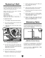
8. Position the blade so that the teeth are facing
to the right and down toward the table, then
slide it through the table slot.
Note: If the teeth will not point downward
in any orientation, the blade is inside out.
Remove the blade and twist it right-side out.
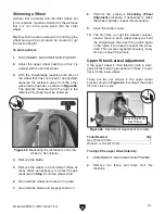
9. Rotate the blade 90°, then slip it over the
wheels while making sure it is properly posi-
tioned between the blade guards and guides.
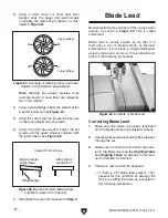
10. Move the blade tension quick release lever
to the right, for rough tensioning the blade.
Using the blade tension adjustment knob and
tension scale, fine tune the tension for the
new blade.
— If you successfully move the quick release
lever to the right and the blade is properly
tensioned, continue with
Step 6.
— If you have difficulty moving the blade
tension quick release lever to the right
or the blade is a different length from the
previous blade, adjust the blade tensioner,
as instructed in the
Blade Tensioner on
Page 54, then continue with Step 6.
11. Adjust the blade tracking (see Blade Tracking
on
Page 21).
12. Adjust the support bearings and the upper/
lower blade guides (see
Adjusting Blade
Support Bearings and Adjusting Blade
Guide Bearings on Pages 26– 27).
13. Close the wheel covers, and replace the table
insert and table pin.
The model G0555LX comes with
3
⁄
8
" eccentrics
(PN P0555LX129) installed behind the guide
bearings. To make guide bearing adjustments
easier when using
1
⁄
8
" blades, a set of
1
⁄
4
" eccen-
trics (PN P0555LX136) has also been included.
The reduced thickness of the
1
⁄
4
" eccentrics pro-
vides more space for guide bearing adjustments
with
1
⁄
8
" blades, helping ensure blade support
bearings will not damage the blade tooth set.
Tool Needed
Qty
Hex Wrench 4mm .............................................. 1
To install
1
⁄
4
" eccentrics:
1. DISCONNECT MACHINE FROM POWER!
2. Put on heavy leather gloves and open wheel
covers. Remove blade as described in
Changing Blade on Page 38.
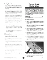
3. Remove (2) guide bearing adjustment cap
screws and guide bearings (see
Figure 51).
Figure 51. Blade support assembly.
Installing
1
⁄
4
"
Eccentrics
Guide Bearing
Adjustment
Cap Screw
Eccentrics
Cap Screw
Guide
Bearing
Guide Shaft Bracket
Summary of Contents for G0555LX
Page 68: ......


