background image

-34-

Model G0505 (Mfg. since 4/04)
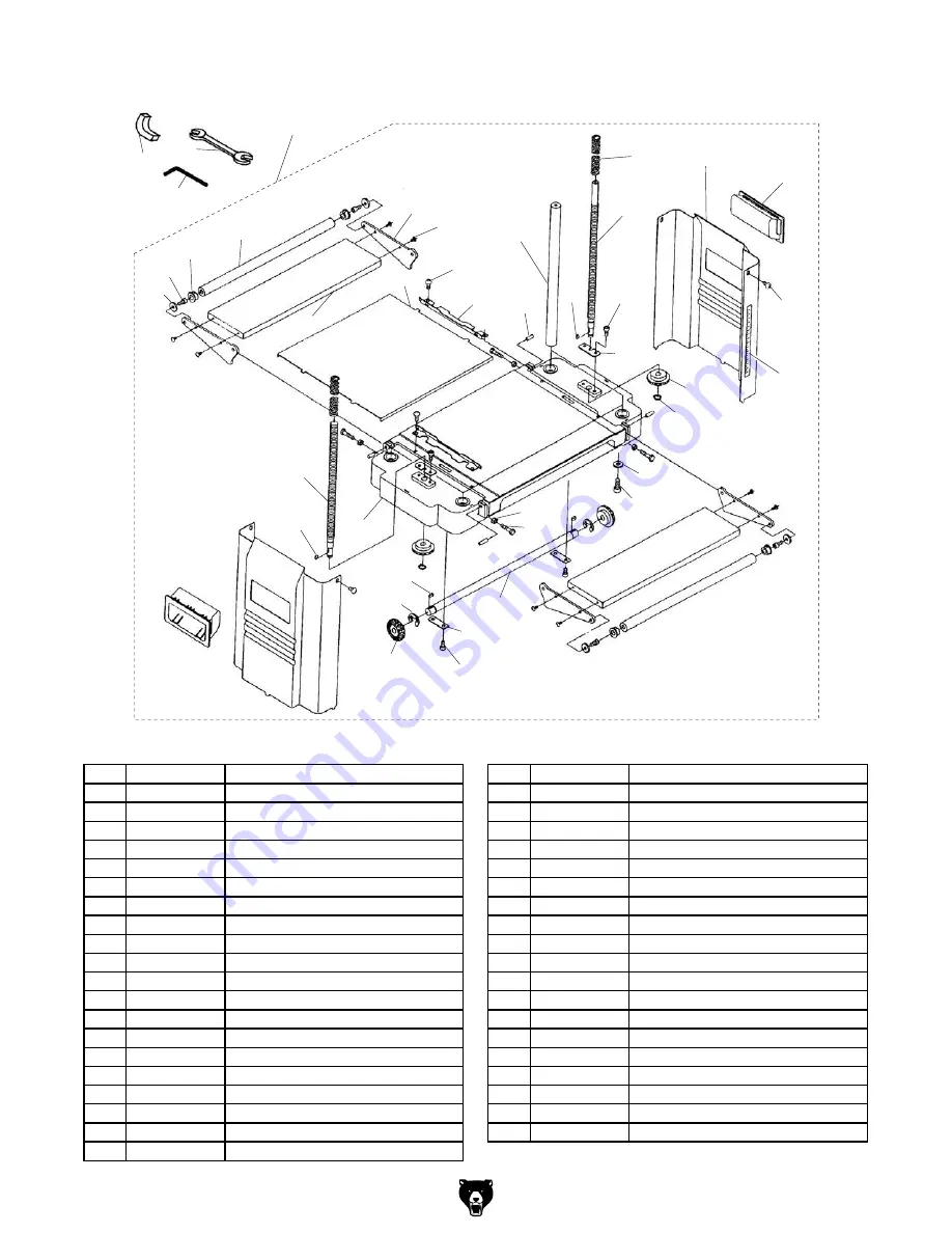
Base Breakdown

200

201

202

203

204

205

206

207

208

209

210

211

212

213

214

215

216

217

218

219

220

221

222

223

224

225

226

227

229

230

231

232

233

234

234A

235

236

237

238

239

228

REF PART #

DESCRIPTION

REF PART #

DESCRIPTION

200

P0505200

BASE ASSEMBLY

221

P0505221

MAIN TABLE

201

P0505201

LEFT LEADSCREW M8-1.25 X 60

222

P0505222

PHLP HD SCR M5-.8 x 8

202

P0505202

KEY 4 X 4 X 8

223

P0505223

GUIDE PLATE

203

P0505203

BEVEL GEAR

224

P0505224

COLUMN

204

P0505204

E-CLIP 8MM

225

P0505225

KEY 4 X 4 X 8

205

P0505205

KEY 4 X 4 X 8

226

P0505226

RIGHT LEADSCREW M10-1.5 X 60

206

P0505206

CAP SCREW M6-1 X 10

227

P0505227

CAP SCREW M6-1 X 10

207

P0505207

FIXING PIECE

228

P0505228

FIXING PIECE

208

P0505208

TRANSMISSION SHAFT

229

P0505229

BEVEL GEAR

209

P0505209

EXTENSION WING BRACKET

230

P0505230

EXT RETAINING RING 10MM

210

P0505210

FLAT WASHER 6MM

231

P0505231

SIDE PANEL

211

P0505211

CAP SCREW M6-1 X 10

232

P0505232

PHLP HD SCR M5-.8 x 6

212

P0505212

EXTENSION WING ROLLER 14-5/16"L

233

P0505233

ROLLER BUSHING

213

P0505213

DEPTH SCALE LABEL

234

P0505234

LEADSCREW SPRING V1.12.02

214

P0505214

HEX BOLT M6-1 X 25

234A P0505234A

LEADSCREW SPRING V2.04.04

215

P0505215

HEX NUT M6-1

235

P0505235

CARRYING HANDLE

216

P0505216

EXTENSION WING

236

P0505236

PHLP HD SCR M4-.7 X 8

217

P0505217

BASE

237

P0505237

RUBBER FOOT

218

P0505218

FLAT WASHER 5/16

238

P0505238

HEX WRENCH 5MM

219

P0505219

CAP SCREW M8-1.25 X 20

239

P0505239

DOUBLE-END WRENCH 8 X 8MM

220

P0505220

ROLL PIN 6 X 20

Summary of Contents for G0505

Page 1: ...OPYRIGHT DECEMBER 2002 BY GRIZZLY INDUSTRIAL INC REVISED JANUARY 2018 HE WARNING NO PORTION OF THIS MANUAL MAY BE REPRODUCED IN ANY SHAPE OR FORM WITHOUT THE WRITTEN APPROVAL OF GRIZZLY INDUSTRIAL INC...

Page 2: ...g grinding tool integrity and the usage of personal protective equipment The manufacturer will not be held liable for injury or property damage from negligence improper training machine modifications...

Page 3: ...s 11 Assembly 13 Test Run 14 SECTION 4 OPERATIONS 15 ON OFF Switch 15 Reset Button 15 Depth of Cut 16 Workpiece Inspection 16 Planing Tips 17 Wood Hardness 17 Cutting Problems 18 Basic Operation 19 SE...

Page 4: ...doubt immediately call our techni cal support for updates or clarification For your convenience we always keep current Grizzly manuals and most updates available on our website at www grizzly com Any...

Page 5: ...e 2 Model G0505 identification Cutterhead Elevation Crank Depth of Cut Scale Return Rollers Infeed Extension Wing Outfeed Extension Wing Cutterhead Motor Assembly Chip Deflector Viewed from the rear o...

Page 6: ...st Ship Upright No Electrical Power Requirement 110V Single Phase 60 Hz Prewired Voltage 110V Full Load Current Rating 15A Minimum Circuit Size 20A Connection Type Cord Plug Power Cord Included Yes Po...

Page 7: ...h 14 1 2 in Construction Table Precision Ground Cast Iron Body Sheet Metal Cutterhead Assembly Steel Infeed Roller Rubber Outfeed Roller Rubber Paint Type Finish Epoxy Other Measurement Scale Inch Met...

Page 8: ...EARING PROPER APPAREL Do not wear clothing apparel or jewelry that can become entangled in moving parts Always tie back or cover long hair Wear non slip footwear to avoid accidental slips which could...

Page 9: ...orly lit areas Keep work area clean dry and well lighted to mini mize risk of injury Safety Instructions for Machinery APPROVED OPERATION Untrained operators can be seriously hurt by machinery Only al...

Page 10: ...slight angle with the wood grain Like all machinery there is potential danger when operating this machine Accidents are fre quently caused by lack of familiarity or failure to pay attention Use this m...

Page 11: ...t it is grounded DO NOT remove ground prong from plug to fit into a two pronged outlet If the plug will not fit the outlet have the proper outlet installed by a qualified electrician Extension Cords W...

Page 12: ...tisfied with the condi tion of your shipment inventory the contents Unpacking This machine and its com ponents are very heavy Get lifting help to move heavy items Inventory The following is a descript...

Page 13: ...nces to the shop or disable start switch or power connection to prevent unsupervised use Site Considerations Figure 5 Minimum working clearances 271 2 22 Mounting Options Your planer has three options...

Page 14: ...ch use the four bolts holes in the base see Figure 6 on the previous page to mount it to the workbench The strongest mounting option is a Through Mount where holes are drilled all the way through the...

Page 15: ...urely in place when the planer is connected to power 3 Use the elevation crank to lower the cutterhead so that you can access the top of the cutterhead assembly from the rear 4 Remove the two wing nut...

Page 16: ...that the machine is setup properly 2 Make sure all tools and objects used during setup are cleared away from the machine 3 Connect the machine to the power source 4 Verify that the machine is operatin...

Page 17: ...of the machine as shown in Figure 13 Figure 13 ON OFF switch with disabling key and reset button Disabling Key Reset Button The switch is equipped with a switch disabling key that when the switch is i...

Page 18: ...with more than 20 moisture content or wood exposed to excessive moisture such as rain or snow will plane poorly and cause excessive wear to the knives and motor Excess moisture can also hasten rust an...

Page 19: ...can effectively take with each pass The chart in Figure 15 shows the Janka Hardness Rating for a number of commonly used species The larger the number the harder the workpiece and the less planer dep...

Page 20: ...ing lumber longer than your finished workpiece length then cutting off the excess after the planing is done Wavy Surface Reason Caused by poor knife height adjust ment The wavy surface appears when on...

Page 21: ...less than 1 4 turn to raise the cutterhead above the workpiece surface approximately 1 32 for the first pass then remove the workpiece from the machine 8 If the workpiece is longer than can be sup por...

Page 22: ...0 001 and can measure outside surfaces inside surfaces and heights depths Features stainless steel shock resistant construction and a dust proof display An absolute treat for the perfection ist Figure...

Page 23: ...19 x 65 long Comes with 9 ball bearing rollers and has four indepen dently adjustable legs for any leveling requirement Adjustable in height from 263 8 to 441 8 Figure 24 SHOP FOX Roller Table G7313...

Page 24: ...gest problem for the knives comes from stock with nails pebbles or other hard embedded objects These items will nick or chip the knives causing permanent dam age Another wear factor is sand grit or ot...

Page 25: ...As you remove the brush assembly make note of the orientation of the carbon tip so that if found acceptable you can re install it the same way Figure 26 Removing the front motor brush assembly Brush...

Page 26: ...Wrench 5mm 1 Phillips Screwdriver 1 Wood Block 4x4 1 To removed trapped sawdust from the feed rollers 1 DISCONNECT PLANER FROM POWER 2 Remove the elevation crank top cover and both side panels from th...

Page 27: ...chine stalls or is underpowered 1 Workpiece material not suitable for machine 2 Belt slipping 3 Plug receptacle at fault 4 Motor brushes at fault 5 Pulley slipping on shaft 6 Motor bearings at fault 7...

Page 28: ...th of cut too great 1 Inspect workpiece for knots and grain direction Page 16 only use clean stock 2 Replace knife Page 27 3 Reduce the depth of cut Inconsistent chipped pattern on workpiece 1 Chips a...

Page 29: ...and can quickly cause a serious injury to your hands or fingers Always wear heavy leather gloves when handling these knives to reduce the risk of cutting injuries 4 With great care slide the knife ou...

Page 30: ...terhead Knife Gauge 7 Apply downward pressure on the gauge against the upward pressure of the springs this will correctly set the knife height at 0 059 1 5mm above the cutterhead 8 While maintaining p...

Page 31: ...bility These wings must be level from side to side with the main table to ensure planing accura cy and to help reduce the amount of end snipe To check adjust the extension wings 1 DISCONNECT PLANER FR...

Page 32: ...Mfg since 4 04 1 2 3 4 5 6 7 8 9 10 11 12 13 14 15 16 17 18 19 20 21 22 23 24 25 26 27 27A 28 29 30 31 32 33 34 35 36 37 38 39 40 40A 41 42 43 44 45 46 47 48 49 50 51 51 1 52 56 57 58 Head Breakdown...

Page 33: ...05013 ROLL PIN 6 X 20 40A P0505040A FEED ROLLER W KEYWAY V1 12 02 14 P0505014 BUSHING 41 P0505041 PHLP HD SCR M5 8 X 10 15 P0505015 ROLLER 42 P0505042 ROLLER BRACKET 16 P0505016 GIB 43 P0505043 ROLLER...

Page 34: ...own 100 100A 101 102 103 104 106 107 108 109 110 111 112 113 114 115 115A 116 117 118 119 120 121 122 123 124 125 126 127 128 129 130 130V2 131 132 133 134 135 136 137 138 140 142 145 146 148 149 151...

Page 35: ...0505138 TAP SCREW 10 X 2 112 P0505112 THREADED BRUSH COVER 140 P0505140 FLAT WASHER 4MM 113 P0505113 SET SCREW M5 8 X 10 142 P0505142 PHLP HD SCR M4 7 X 8 114 P0505114 GEAR BOX COVER 145 P0505145 EXT...

Page 36: ...M6 1 X 10 207 P0505207 FIXING PIECE 228 P0505228 FIXING PIECE 208 P0505208 TRANSMISSION SHAFT 229 P0505229 BEVEL GEAR 209 P0505209 EXTENSION WING BRACKET 230 P0505230 EXT RETAINING RING 10MM 210 P050...

Page 37: ...metalworker ____ 0 2 Years ____ 2 8 Years ____ 8 20 Years ____20 Years 6 How many of your machines or tools are Grizzly ____ 0 2 ____ 3 5 ____ 6 9 ____10 7 Do you think your machine represents a good...

Page 38: ...LINE FOLD ALONG DOTTED LINE GRIZZLY INDUSTRIAL INC P O BOX 2069 BELLINGHAM WA 98227 2069 Place Stamp Here Name_______________________________ Street_______________________________ City______________S...

Page 39: ...tried in the State of Washington County of Whatcom We shall in no event be liable for death injuries to persons or property or for incidental contingent special or consequential damages arising from...

Page 40: ......

Reviews: