Grizzly EXTREME G0513X2B Manual Download Page 15

Model g0513X2B (Mfg. since 5/11)

-15-

to  lubricate  the  tension  adjustment  assem-

bly:

1.  disConneCt BAndsAW FroM poWer!

2.  open  the  top  wheel  cover  and  look  through 

the top of the wheel. 

3.  Wipe  off  any  existing  grease  and  sawdust 

buildup  on  the  blade  tension  adjustment 
assembly and tension lever cam.

4.  Apply  a  thin  coat  of  grease  to  the  tension 

adjustment assembly and tension lever cam 
(see 

figure 12).

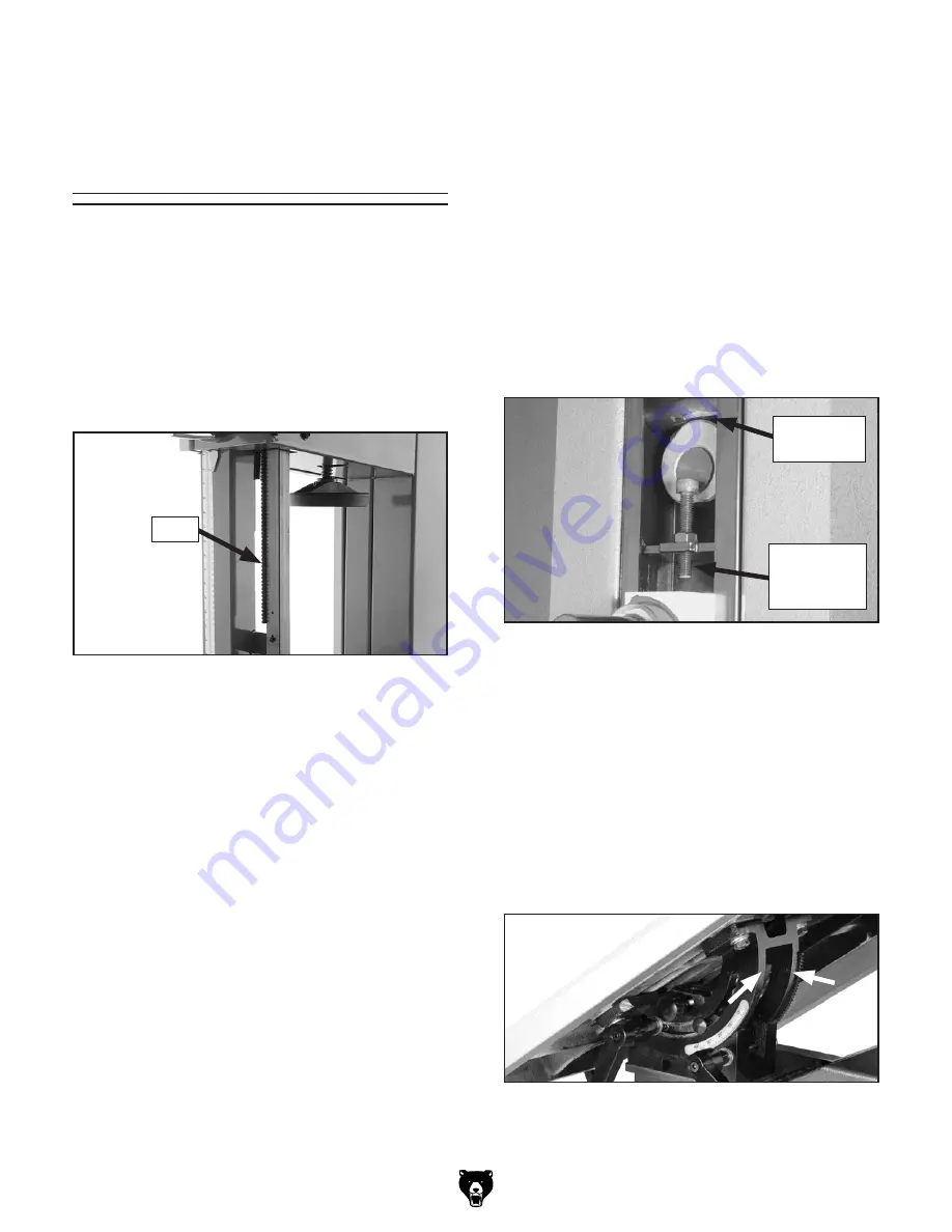
figure 12. tension adjustment assembly 

locations (top wheel removed for clarity).

to lubricate the trunnions:

1.  disConneCt BAndsAW FroM poWer!

2.  Move the table up until it reaches its maximum 

45˚ angle and wipe off all excess grease and 
sawdust from the trunnions.

3.  Apply a thin coat of light all purpose grease to 

the trunnions (see 

figure 13).

figure 13. trunnion lubrication location.

4.  Move the table down and up to distribute the 

grease, then wipe off any excess grease.

to lubricate the blade guide rack and pinion:

1.  disConneCt BAndsAW FroM poWer!

2.  lower  the  blade  guide  until  it  reaches  the 

table.

3.  Wipe  off  any  existing  grease  and  sawdust 

buildup on the rack (see 

figure 11).

figure 11. rack lubrication location.

4.  Apply a thin coat of light all-purpose grease to 

the rack.

5.  Move  the  blade  guide  up  and  down  several 

times  to  distribute  the  grease,  then  remove 
any  excess  grease  to  help  prevent  sawdust 
buildup.

to lubricate the blade tracking knob:

1.  disConneCt BAndsAW FroM poWer!

2.  loosen  the  blade  tracking  lock  lever,  then 

unscrew the blade tracking knob 5 turns.

3.  Wipe  off  any  existing  grease  and  sawdust 

buildup on the threads.

4.  Apply a few dabs of a light all-purpose grease 

to the threads.

5.  re-adjust  tracking  (see  blade  tracking  on 

g0513X Manual 

page 22).

(Replaces 

Lubrication on Page 

45)

rack

tension 

lever Cam

tension 

Adjustment 

Assembly

Summary of Contents for EXTREME G0513X2B

Page 1: ...dures the wiring diagram and parts in this insert the content in the Model G0513X owner s manual is the same for both machines On the following pages the header indicates which page it replaces in the...

Page 2: ...th 27 x 17 3 4 in Shipping Dimensions Type Wood Slat Crate Content Machine Weight 446 lbs Length x Width x Height 31 x 20 x 81 in Electrical Power Requirement 220V Single Phase 60 Hz Full Load Current...

Page 3: ...One Piece Reinforced Steel Upper Wheel Computer Balanced Cast Iron Lower Wheel Computer Balanced Cast Iron Tire Polyurethane Wheel Cover Pre Formed Steel Paint Powder Coated Other Related Information...

Page 4: ...e influence of drugs or alcohol when tired or when distracted OWNER S MANUAL Read and understand this owner s manual BEFORE using machine Untrained users can be seriously hurt EYE PROTECTION Always we...

Page 5: ...not force machine It will do the job safer and better at the rate for which it was designed GUARDS COVERS Guards and covers can protect you from accidental contact with moving parts or flying debris...

Page 6: ...ou need to back the workpiece out turn the bandsaw OFF and wait for the blade to come to a complete stop DO NOT twist or put excessive stress on the blade that could damage it LEAVING WORK AREA Never...

Page 7: ...ly if connected to an undersized circuit To reduce the risk of these hazards avoid over loading the machine during operation and make sure it is connected to a power supply circuit that meets the requ...

Page 8: ...h green insulation with or without yellow stripes is the equipment grounding wire If repair or replacement of the power cord or plug is nec essary do not connect the equipment grounding wire to a live...

Page 9: ...ents Figure 2 Qty A Bandsaw not shown 1 B Table w Table Insert 1 C Miter Gauge 1 D Resaw Fence 1 E Front Square Rail 1 F Fence Assembly 1 G Guide Post Handwheel 1 B C D E F G The following is a descri...

Page 10: ...her Figure 3 Replaces Table on Page 21 Replaces Installing Fence on Page 25 Components and Hardware Needed Qty Hex Bolts M8 1 25 x 25 4 1 Follow Steps 1 3 on Page 21 in the G0513X Manual If the table...

Page 11: ...Hex Nut Fence Handle Secure the guide post handwheel onto the flat part of the handwheel shaft with the M6 1 x 20 cap screw Guide Post Handwheel Children or untrained people can be killed or seriousl...

Page 12: ...ty feature is not working correctly This safety feature must work properly before proceeding with regular operations Call Tech Support for help 5 Twist the OFF button clockwise so it pops out When the...

Page 13: ...ce parallel with the miter slot 1 DISCONNECT BANDSAW FROM POWER 2 Make sure the miter slot is aligned with the bandsaw blade refer to Aligning Table on G0513X Manual Page 30 3 If the fence is mounted...

Page 14: ...ence is mounted on the right hand side of the blade remove it and re install it on the left hand side of the blade 2 Place the fence flush against the bandsaw blade Figure 9 Figure 9 Fence flush with...

Page 15: ...cation 4 Move the table down and up to distribute the grease then wipe off any excess grease To lubricate the blade guide rack and pinion 1 DISCONNECT BANDSAW FROM POWER 2 Lower the blade guide until...

Page 16: ...e 1 DISCONNECT BANDSAW FROM POWER 2 Remove the motor fan cover then loosen the cap screws securing the motor fan and brake shoe see Figure 14 Figure 14 Adjusting distance between magnetic brake and br...

Page 17: ...ese diagrams is current at the time of printing but may not match your machine If you find this to be the case use the wiring diagram inside the motor junction box CAPACITORS INVERTERS Some capacitors...

Page 18: ...18 Model G0513X2B Mfg Since 5 11 READ ELECTRICAL SAFETY ON PAGE 17 G0513X2B Electrical Components Figure 16 Motor wiring Figure 15 Control panel wiring Figure 17 Magnetic switch...

Page 19: ...X Ground Hot Hot 6 15 PLUG as recommended 220 VAC L2 L1 Magnetic Brake YZG G Run Capacitor 45MFD 450VAC 95 Ground T1 2 T3 6 NO14 T2 4 L1 1 L3 5 NO13 L2 3 NC15 SDE NC16 SDE MA 18 AMP RESET 96 98 1 2 3...

Page 20: ...1 21 22 22 23 24 24 25 28 29 30 31 32 33 34 35 36 37 38 39 39 40 41 42 43 44 45 46 47 48 119 48 49 50 50 51 55 56 57 58 60 60 61 61 61 61 62 63 64 65 66 67 68 78 79 80 81 82 83 83 84 84 85 86 87 88 89...

Page 21: ...3 RELAY SDE RA 20 8 12 79 PSS09M SET SCREW M8 1 25 X 20 19 4 P0513X2B019 4 MAG SWITCH FRONT COVER 80 PN03M HEX NUT M8 1 25 19 5 P0513X2B019 5 POWER CORD 14AWG X 3C 81 P0513081 LOWER WHEEL SHAFT 19 6V...

Page 22: ...N 170 PFS09M FLANGE SCREW M5 8 X 50 174 P0513X2B174 TERMINAL BOX 171 PS38M PHLP HD SCR M4 7 X 10 175 P0513X2B175 WIRE NUT P3 172 PTLW02M EXT TOOTH WASHER 5MM 176 PFS07M FLANGE SCREW M5 8 X 10 173 P051...

Page 23: ...50 2 150 3 150 4 150 5 150 6 150 7 150 8 151 151 10 151 4 151 5 151 6 151 7 151 8 151 9 167 168 169 126 156 156 1 156 2 156 4 156 3 163 165V2 164 162 161 161 1 160 158 158 159 153 154 157 157 1 157 12...

Page 24: ...1M SET SCREW M8 1 25 X 25 145 15 P0513X124 COVER 157 4 P0513X2B157 4 SPRING PIECE 145 16 PCAP11M CAP SCREW M8 1 25 X 16 157 5 PFS17M FLANGE SCREW M4 7 X 8 145 17 PFH31M FLAT HD SCR M4 7 X 8 157 6 P051...

Page 25: ...ASHER 8MM 155 20V2 PFH30M FLAT HD SCR M5 8 X 8 155 2 PLN04M LOCK NUT M8 1 25 155 21 PSB01M CAP SCREW M6 1 X 16 155 3 PS17M PHLP HD SCR M4 7 x 6 155 22 PSB37M CAP SCREW M6 1 X 50 155 4 P0513115 GEAR PL...

Page 26: ...or www grizzly com to order new labels REF PART DESCRIPTION REF PART DESCRIPTION 201 P0513X2B201 G0513X2B MODEL LABEL 209 PLABEL 14 ELECTRICITY LABEL 202 G8588 GRIZZLY LOGO PLATE 210 P0513X210 EXTREM...

Page 27: ...ecommended for this machine by Grizzly NOTICE Refer to the newest copy of the Grizzly Catalog for other accessories available for this machine G5562 SLIPIT 1 Qt Gel G5563 SLIPIT 12 oz Spray G2871 Boes...

Page 28: ...Buy Direct and Save with Grizzly Trusted Proven and a Great Value Since 1983 ORDER 24 HOURS A DAY 1 800 523 4777 Visit Our Website Today For Current Specials...

Page 29: ...SAW OWNER S MANUAL COPYRIGHT JANUARY 2006 BY GRIZZLY INDUSTRIAL INC REVISED FEBRUARY 2007 TR WARNING NO PORTION OF THIS MANUAL MAY BE REPRODUCED IN ANY SHAPE OR FORM WITHOUT THE WRITTEN APPROVAL OF GR...

Page 30: ......

Page 31: ...Unpacking 16 Inventory 17 Hardware Recognition Chart 18 Clean Up 19 Site Considerations 19 Moving Placing Base Unit 20 Mounting 20 Table 21 Blade Tracking 22 Positive Stop 23 Dust Collection 24 Instal...

Page 32: ...50 Adjusting Wheel Brush 50 Wheel Alignment 51 G0513X Electrical Components 53 G0513X Wiring Diagram 54 G0514X Electrical Components 55 G0514X Wiring Diagram 56 G0514X3 Electrical Components 57 G0514...

Page 33: ...es set forth in this manual you can expect years of trouble free enjoyable operation and proof of Grizzly s commitment to customer satisfaction We are pleased to provide this manual with the Model G05...

Page 34: ...4 lbs Length Width Height 31 x 20 x 81 in Electrical Switch On Off Push Button Switch Voltage 110 220V Cord Length 6 ft Cord Gauge 14 gauge Recommended Breaker Size 30 amps at 110V 15 amps at 220V Plu...

Page 35: ...luminum Resaw Fence Base Construction Formed Steel Body Construction Formed Steel Upper Wheel Computer Balanced Cast Iron Lower Wheel Computer Balanced Cast Iron Tire Material Polyurethane Wheel Cover...

Page 36: ...e Wood Slat Crate Content Machine Weight 460 lbs Length Width Height 21 x 33 x 85 in Electrical Switch Magnetic with Thermal Overload Protection Switch Voltage 220V Cord Gauge 14 gauge Recommended Bre...

Page 37: ...minum Resaw Fence Base Construction Formed Steel Body Construction Formed Steel Upper Wheel Computer Balanced Cast Iron Lower Wheel Computer Balanced Cast Iron Tire Material Polyurethane Wheel Cover P...

Page 38: ...Content Machine Weight 456 lbs Length Width Height 21 x 33 x 85 in Electrical Switch Magnetic with Thermal Overload Protection Switch Voltage 220V Cord Gauge 14 gauge Recommended Breaker Size 10 amp...

Page 39: ...truded Aluminum Resaw Fence Base Construction Formed Steel Body Construction Formed Steel Upper Wheel Computer Balanced Cast Iron Lower Wheel Computer Balanced Cast Iron Tire Material Polyurethane Whe...

Page 40: ...F Miter Gauge G Blade Tension Handwheel H Ball Bearing Roller Guides I Guide Post J Guide Post Handwheel K Blade Tracking Window Identification L Quick Release Blade Tension Lever M Blade Tracking Kn...

Page 41: ...rcinogen and can cause cancer and severe respiratory illnesses For Your Own Safety Read Instruction Manual Before Operating this Machine The purpose of safety symbols is to attract your attention to p...

Page 42: ...ng accessories 16 MAKE SURE GUARDS ARE IN PLACE AND WORK CORRECTLY BEFORE USING MACHINERY Safety Instructions for Machinery 17 REMOVE ADJUSTING KEYS AND WRENCHES Make a habit of checking for keys and...

Page 43: ...required 2 HAND PLACEMENT Never position fin gers or thumbs in line with the cut Serious personal injury could occur 3 GUARDS Do not operate this bandsaw without the blade guard in place or with the...

Page 44: ...to connect your machine to a shared cir cuit you may create a fire hazard consult a qualified electrician to reduce this risk G0513X at 220V 15 Amp Circuit Breaker G0513X at 110V 30 Amp Circuit Breake...

Page 45: ...d that does not exceed 50 feet in length 220V Operation Use at least a 12 gauge cord that does not exceed 50 feet in length 440V Operation Do not use an extension cord with 440V Extension Cords Ground...

Page 46: ...amiliar with the controls and opera tions before starting the machine Unpacking Set Up Safety SECTION 3 SET UP The following items are needed to complete the set up process but are not included with y...

Page 47: ...Cap Screws M6 1 x 16 Fence 2 Hex Bolts M6 1 x 20 Fence 2 Fence Handle M8 1 25 x 22 Fence 1 Lock Washers 6mm Fence 2 Flat Washers 6mm Fence 2 Rail Pad M6 x 18 Fence 1 Hex Nut M6 1 Fence 1 Lock Handle...

Page 48: ...18 G0513X G0514X G0514X3 Extreme Series Bandsaw Hardware Recognition Chart...

Page 49: ...ing with a sol vent cleaner or citrus based degreaser such as Grizzly s G7895 Degreaser To clean thoroughly some parts may need to be removed For opti mum performance from your machine make sure you c...

Page 50: ...e way in then place the lifting hook through the eye bolt and lift slowly with a forklift 4 Remove the pallet and slowly set the bandsaw into position We recommend mounting your new machine to the flo...

Page 51: ...d to make table installation easier Components and Hardware Needed Qty Table 1 Hex Bolts M8 1 25 x 16 4 Lock Washers 8mm 4 Flat Washers 8mm 4 Table Pin 1 Table Insert 1 To install the table 1 Loosen b...

Page 52: ...Engage the quick tension lever and turn the blade tension handwheel until the tension scale Figure 16 reads between 4 and 6 Figure 16 Blade tensioning controls Blade Centered on Peak of Crown Blade C...

Page 53: ...y or death can occur if the bandsaw starts during table adjust ments Disconnect power from the bandsaw before performing table adjust ments Figure 19 Installed positive stop bolt Positive Stop Figure...

Page 54: ...tached to dust port Dust Collection Recommended CFM at Each Dust Port 400 Do not confuse this CFM recommendation with the rating of the dust collector To determine the CFM at the dust port you must ta...

Page 55: ...ce 1 Cap Screws M6 1 x 16 2 Hex Bolts M6 1 x 20 2 Lock Washers 6mm 2 Flat Washers 6mm 2 Fence Handle M8 1 25 x 22 1 Hex Nut M8 1 25 1 Rail Pad M6 1 x 18 1 Hex Nut M6 1 1 Flat Washer 8mm 1 Lock Handle...

Page 56: ...table insert 3 Refer to CIRCUIT REQUIREMENTS on Page 14 and connect the plug to the power cord 4 Make sure that any tools or foreign objects have been removed from the machine 5 Plug the machine into...

Page 57: ...reads and use that as a guide for tensioning that blade in the future Note Always detension the blade after use to increase blade life and reduce strain on the bandsaw components 8 Re adjust the blad...

Page 58: ...igure 30 Dollar bill folded twice to make an approximate 0 016 gauge Note For a quick gauge fold a dollar bill in half twice four thicknesses of a dollar bill is approxi mately 0 016 and place it betw...

Page 59: ...earing Rotation Adjustment Cap Screw 4 Check to make sure the guide block assem bly is perpendicular with the face of the sup port bearing as illustrated in Figure 28 If the guide block assembly is pe...

Page 60: ...ng Table To ensure cutting accuracy when the table is first installed the table should be aligned so that the miter slot is parallel to the bandsaw blade This procedure works best with a 3 4 blade ins...

Page 61: ...a machinist s square with one edge against the face of the miter gauge and the other against the blade face as shown in Figure 36 2 Loosen the lock knob on the miter gauge and adjust it flush with th...

Page 62: ...utting tools in the shop It is capable of perform ing many different cutting functions including Straight Cuts Miters Angles Compound Angles Resawing Ripping Crosscutting Irregular Cuts Simple and Com...

Page 63: ...ide post until the upper blade guide assembly is within 1 from the top of the workpiece 4 Lock the guide post in place with the lock knob Guide Post Figure 39 Guide post controls The guide post shown...

Page 64: ...venient to replace the blade compensate for lead by skewing the fence or adjusting the table To skew your fence 1 Cut a piece of scrap wood approximately 3 4 thick x 3 wide x 17 long On a wide face of...

Page 65: ...mounting bolts Shift the table to compensate for the blade lead then retighten the table bolts 5 Repeat Steps 1 4 until the blade cuts straight Personal injury or death can occur if the bandsaw starts...

Page 66: ...ration Figure 44 Crosscutting with miter gauge Ripping Ripping is the process of cutting with the grain of the wood stock For plywood and other pro cessed wood ripping simply means cutting down the le...

Page 67: ...ce 1 Verify that the bandsaw is setup properly and that the table is perpendicular to the blade 2 Use the widest blade your bandsaw will accept Note The blade must also be sharp and clean 3 Install th...

Page 68: ...to bind 5 Cut the stack of pieces as though you were cutting a single piece Follow your layout line with the blade kerf on the waste side of your line as shown in Figure 46 Figure 46 Typical stacked c...

Page 69: ...nally smooth cut is desired To adjust the blade speed 1 DISCONNECT BANDSAW FROM POWER 2 Loosen the motor mount cap screws shown in Figure 47 and rotate the motor to loosen the V belt 3 Refer to Figure...

Page 70: ...ius curve that will be cut on your workpiece and use the cor responding blade width Figure 50 Blade width radii Figure 51 Raker Skip Hook tooth styles Raker Skip Hook Straight Cutting Use the largest...

Page 71: ...pitch for each application The wrong choice of blades will often produce unnecessary heat which will shorten the life of your blade A clean blade will perform much better than a dirty blade Dirty or g...

Page 72: ...ther gloves when handling saw blades Figure 52 Placing blade on the wheels 3 Tighten the blade tension lever 4 Apply tension to the blade by turning the ten sion control knob Rotate the upper wheel sl...

Page 73: ...1311 2 Carbide Tipped Replacement Blades for the Model G0513X MODEL WIDTH TPI H4897 3 8 3 4 VP H4898 1 2 3 H4899 3 4 3 H4900 1 2 3 VP H4901 1 3 4 VP 143 Carbon Steel Replacement Blades for the Model...

Page 74: ...ned earmuffs Especially important if you or employees operate for hours at a time H1302 H4977 H4979 H2347 H1300 Figure 55 Half mask respirator and disposable cartridge filters H2499 Small Half Mask Re...

Page 75: ...remove it Treat all unpainted cast iron and steel with a non staining lubricant after cleaning Cleaning Protect the unpainted cast iron surfaces on the table by wiping the table clean after every use...

Page 76: ...disconnected con nections and repair replace as necessary 7 Test replace if faulty 8 Repair replace Machine stalls or is underpow ered 1 Wrong workpiece material wood 2 Processing speed too fast for...

Page 77: ...lution Machine slows when operating 1 Feeding workpiece too fast 2 Blade is dull 1 Reduce feed rate See Basic Cutting Tips on Page 32 2 Replace blade Page 42 Ticking sound when the saw is running 1 Bl...

Page 78: ...er of the V belt Note the amount of deflection Figure 57 If deflec tion is more than 3 4 tighten the V belt Tensioning V Belt Tools Needed Qty Hex Wrench 6mm 1 To tension the V belt 1 DISCONNECT BANDS...

Page 79: ...ount bolt Wheel Mount Bolt 5 Rotate the motor to release the tension on the V belt and pull it off of the motor pulley 6 Slip the old V belt off of the wheel pulley and install the new V belt in its p...

Page 80: ...lever to the tightened posi tion 5 Turn the adjustment screw shown in Figure 60 until the gap between the screw and the wheel shaft hinge is 1 16 3 16 Adjusting Wheel Brush The lower wheel compartmen...

Page 81: ...wheels automatically track the blade by balancing it on the crown of the wheel This is known as coplanar tracking To check if your wheels are coplanar 1 Make the Coplanarity Gauge shown in Figure 62...

Page 82: ...n your wheels are copla nar readjust the guide blocks and rear sup port bearings and replace the wheel cov ers Note The blade may track slightly off center when the wheels are coplanar This is natural...

Page 83: ...G0513X G0514X G0514X3 Extreme Series Bandsaw 53 G0513X Electrical Components Switch Wiring Motor Wiring To Power Supply To Motor...

Page 84: ...54 G0513X G0514X G0514X3 Extreme Series Bandsaw G0513X Wiring Diagram G0513X Wiring Diagram...

Page 85: ...0514X G0514X3 Extreme Series Bandsaw 55 G0514X Electrical Components Power Supply Junction Block Motor Wiring Control Panel Wiring Magnetic Switch Wiring To Motor To Junction Box To Control Panel POWE...

Page 86: ...56 G0513X G0514X G0514X3 Extreme Series Bandsaw G0514X Wiring Diagram...

Page 87: ...4X G0514X3 Extreme Series Bandsaw 57 G0514X3 Electrical Components Motor Wiring 220V Control Panel Wiring POWER ON OFF Magnetic Switch Wiring To Motor To Junction Box To Control Panel Power Supply Jun...

Page 88: ...58 G0513X G0514X G0514X3 Extreme Series Bandsaw G0514X3 Wiring Diagram G0514X3 Wiring Diagram...

Page 89: ...G0513X G0514X G0514X3 Extreme Series Bandsaw 59 G0513X Main Parts...

Page 90: ...60 G0513X G0514X G0514X3 Extreme Series Bandsaw G0513X Fence Guide Parts...

Page 91: ...M8 1 25 X 20 78 P0513078 COVER 26 P0513X026 TIRE 79 PSS09M SET SCREW M8 1 25 X 20 27 P0513X027 LOWER WHEEL 17 80 PN03M HEX NUT M8 1 25 28 P0513X028 IDLE PULLEY 81 P0513081 LOWER WHEEL SHAFT 29 PN32 HE...

Page 92: ...7587003 FIXED SHAFT 146 P0513X146 HANDWHEEL 121 4 PH7587004 SHAFT 147 PSB02M CAP SCREW M6 1 X 20 121 5 PH7587005 SPRING PIECE 148 PCB10M CARRIAGE BOLT M8 1 25 X 85 121 6 PH7528004 LOCK HANDLE M8 X 44...

Page 93: ...com to order new labels REF PART DESCRIPTION REF PART DESCRIPTION 201 P0513X201 G0513X MODEL LABEL 209 PLABEL 14 ELECTRICITY LABEL 202 G8588 GRIZZLY LOGO PLATE 210 P0513X210 EXTREME SERIES PLATE 203 P...

Page 94: ...64 G0513X G0514X G0514X3 Extreme Series Bandsaw G0514X G0514X3 Main Parts...

Page 95: ...G0513X G0514X G0514X3 Extreme Series Bandsaw 65 G0514X G0514X3 Fence Guide Parts...

Page 96: ...zards and ways to prevent injury The owner of this machine MUST maintain the original location and readability of the labels on the machine If any label is removed or becomes unreadable REPLACE that l...

Page 97: ...9 CAM 23 P0514023 SAW BLADE 6TPI 143 70 P0513070 PILLOW BLOCK 24 PLW04M LOCK WASHER 8MM 71 P0513071 HANDLE M10 1 5 25 PSB14M CAP SCREW M8 1 25 X 20 72 P0513072 LEVER ROD 26 P0514X026 TIRE 73 PN09M HEX...

Page 98: ...T M6 1 103 PLW06M LOCK WASHER 10MM 125 23 PLW03M LOCK WASHER 6MM 104 PW04M FLAT WASHER 10MM 125 24 PSB01M CAP SCREW M6 1 X 16 105 PB18M HEX BOLT M6 1 X 20 125 25 PB08M HEX BOLT M6 1 X 20 106 PSB30M CA...

Page 99: ...BIAS SHAFT 201 P0514X201 G0514X MODEL LABEL 152 7 PR05M EXT RETAINING RING 15MM 201 P0514X3201 G0514X3 MODEL LABEL 152 8 P6202 BALL BEARING 6202ZZ 202 G8589 GRIZZLY LOGO PLATE 152 9 P0513X150 9 HANDL...

Page 100: ...izzly shall be tried in the State of Washington County of Whatcom We shall in no event be liable for death injuries to persons or property or for incidental contingent special or consequential damages...

Page 101: ......

Page 102: ......

Page 103: ......

Page 104: ...Buy Direct and Save with Grizzly Trusted Proven and a Great Value Since 1983 ORDER 24 HOURS A DAY 1 800 523 4777 Visit Our Website Today For Current Specials...

Reviews: