


COMPONENT MAINTENANCE MANUAL
IN 1502H RADAR INDICATOR
TM109102
1-9
May/01
Since the field sync (Y-retrace) pulses must start halfway through the 313th line in the
625-line system, half-line pulses must be provided to the indicator for synchronization.
The field sync pulse for the CCIR system consists of five broad half-line pulses. It
must be inserted following lines 312 1/2 and 625. These broad pulses are preceded
by five equalizing half-line pulses at black level to ensure that the picture signal has no
influence on the field sync pulses at the receiver. The equalizing pulses are repeated
for 2-1/2 lines after the broad pulses and black level is maintained for 18 to 22 lines,
plus line blanking time (12 microseconds). This cuts off the picture tube electron
beam while flyback of the vertical sweep circuit returns the beam to the starting point
for the next field.
The duration of the CCIR line, including the blank line, is 64 microseconds. Details of
the line sync pulse are shown in Figure 1-3. As shown, the duration of the front porch
is 1.3 to 1.8 microseconds at black level. It prevents any change in picture tube level
at the end of the previous line from causing premature triggering of the horizontal
retrace. A back porch of 5.1 to 6.5 microseconds ensures that a sluggish horizontal
flyback does not cause a fold in the displaying picture. The width of the equalizing
pulse is 2.2 to 2.4 microseconds and that of the broad pulse is 27.1 to 27.5
microseconds.
At 64 microseconds per line and 312.5 lines per field, each field is completed in 20
milliseconds for a rate of 50 fields per second. Since vertical retrace and
synchronizing periods occupy the time of several line scans (see Figure 1-3). This
means that fewer than 625 lines are actually available for picture information in each
frame.
(2) RS-170 Video Signal Format
The RS-170 video signal is similar to the CCIR except that it consists of a 525-line,
60-field picture signal. Therefore, the timing is different. See Figure 1-4.
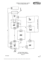
3. Block Diagram Discussion
Figure 1-5 is a block diagram of the IN 1502H Radar Indicator. The block diagram discussion
that follows is divided into the major subassemblies and PC boards of the unit.
A. Video/RS-170 Module
Major circuits of the video/RS-170 module include line receivers for inputs from the
interface unit, composite video processing circuitry, video amplifiers, a brightness circuit
and a degaussing circuit. The power on/off circuit for the indicator is also located on the
video/RS-170 module.
The on/off circuit isolates the power supply at the interface unit from the power supply at
the indicator. It turns the low voltage power supply (LVPS) of the indicator on and off in
response to two inputs from the interface unit. When the aircraft 28 Vdc source is on, the
28 Vdc is always applied to the LVPS. When the radar system is turned on at the control
unit, the on/off line from the control unit to the interface unit is grounded to switch on the
power supply at the interface unit. The ground from the control unit is routed to the
indicator over the IND ON (indicator on) line.
The document reference is online, please check the correspondence between the online documentation and the printed version.


