


TIANJIN GREWIN TECHNOLOGY CO.,LTD.
Web:www.grewin-tech.com Wh86-13072088960
Email:[email protected]
Address:DongLi Distr Tianjin City, China
Tel:
+86-22-84943756
6
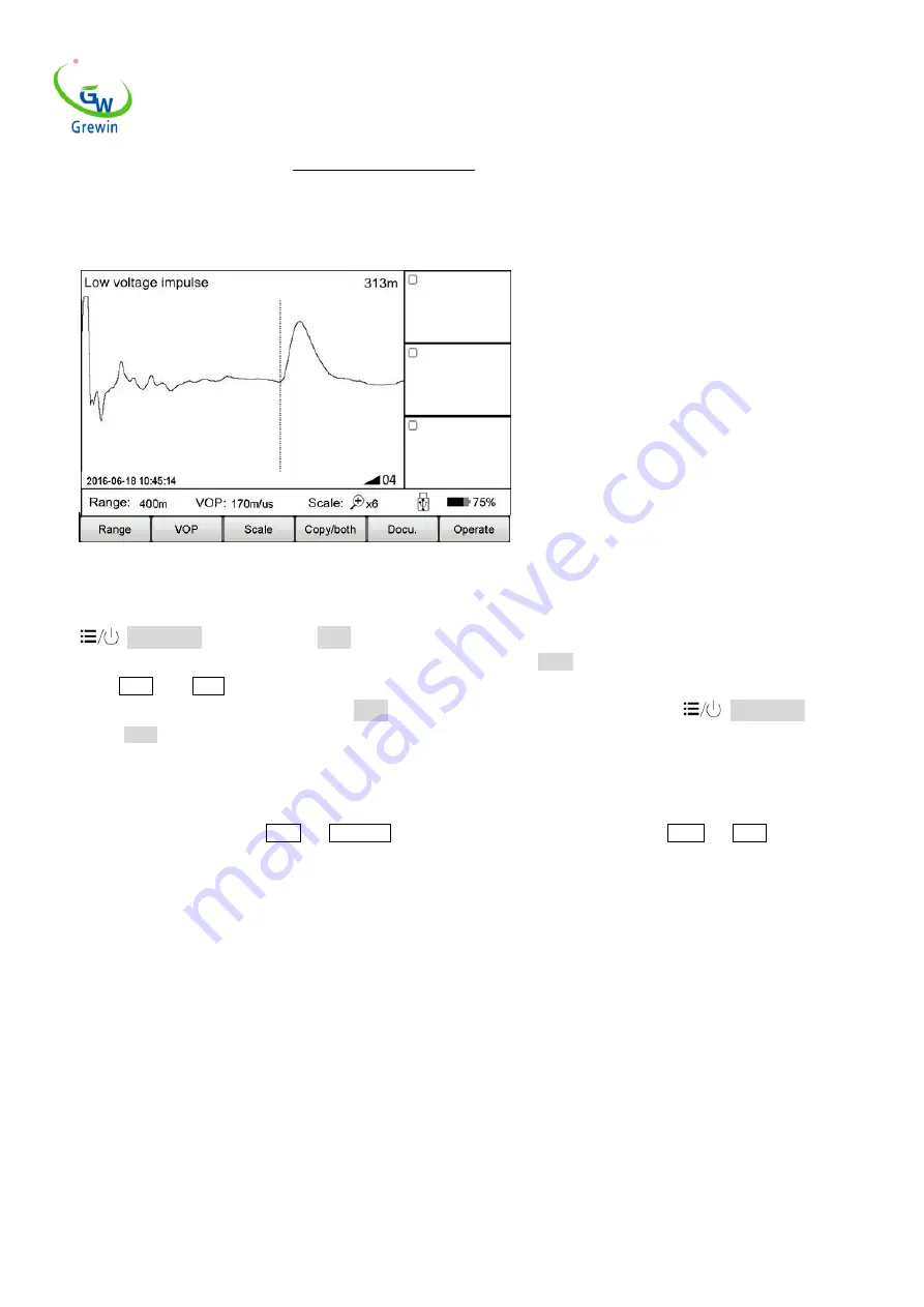
auto test again after modify the range. The testing waveform as below Fig.2.4
Mechanical button operation as below:
Click
Power/Menu button to enter the Menu mode. Current menu will highlight in the main menu and automatically appear pop-up
sub-menu. Use the multiple function button Left/Right button to choose main menu as Range ,and use the Up/Down button to choose the
sub-menu as 400m. Press Enter button to change the range as 400m and automatically exit the sub-menu. Check the testing range, it’s 400m so
the modify is successful and will automatically exit the Menu mode. If no execution any sub-menu and click the
Power/Menu button again,
it will exit the Menu mode.
Summing up above points, menu operation steps are as below:
- choose the main menu, and press the corresponding sub-menu
- choose the sub-menu, and press the corresponding button
In the following,we will all use the way Menu
—
sub-menu to introduce the operation steps.
(
For example, Range
—
200m
)
2.4
Basic operation
2.4.1 Choose the testing range
Testing range is the device measuring distance.
For TDRL or ARM
(multiple impulse method):
For the initial testing, the range should be hundreds meters longer than the cable complete length, for example,if the cable is 1400m, it’s suggested
to choose 3000m but no 1500m. If the suspect point is close, it is suggest to reduce the testing range.
For Impulse current mode:
When initial testing,the range should be triple of the cable length. For example, if the cable is 200m, it is suggested to choose 800m.If the suspect
point is close, it is suggest to reduce the testing range.
For testing range chosen:
Choose Range menu to choose different range, total 10 levels from min. 200m to max. 100km,refer below Fig. 2.5
Fig.2.4 Working interface