HID6506 Rotary Impact Drill
Greenlee / A Textron Company
4455 Boeing Dr. • Rockford, IL 61109-2988 USA • 815-397-7070
7
Inspection
Clean all parts with an appropriate cleaning solution
and dry them thoroughly. Inspect each component as
described in this section. Replace any component that
shows wear or damage.
1. Rotary Impact Assembly: Inspect the exterior for
damage and loose or missing parts. Inspect the
spur gear (through the small view hole in the end of
the mechanism) for grooves, nicks and chips. If the
unit is damaged, replace the impact assembly.
2. Bearings: Insert shaft into bearings. Spin shaft. If
the shaft does not spin smoothly, replace the entire
assembly with bearings already pressed in.
3. Motor Cap, Handle, and Adapter: Inspect mating
surfaces, bores, oil passageways, etc. for grooves
or nicks. If any component shows wear or damage,
replace the entire assembly with bearings already
pressed in.
4. Planet Gear with Needle Bearings: Insert a corre-
sponding dowel pin into the bearing. While holding
the dowel between a thumb and forefinger, roll the
gear in the palm of your other hand. If either gear
does not spin smoothly, replace both gears with
bearings already pressed in.
5. Inspect all other disassembled components for
cracks, grooves or nicks.
Assembly
Refer to the Illustrations and Parts Lists for correct
orientation and placement of parts.
Replace any O-rings, V-rings, seals, and gaskets on
parts that have been disassembled. Apply hydraulic
fluid or O-ring lubricant to all O-rings and all metal
surfaces which they must slide over. When installing
an O-ring which must slide over sharp surfaces, use a
rolling motion and be careful not to damage the O-ring.
Wherever the assembly results in metal-to-metal
contact, coat the surfaces with hydraulic fluid or O-ring
lubricant.
Some steps of the assembly procedure require a remov-
able type of thread sealing and locking compound, such
as Loctite
®
242 or equivalent. Follow the manufacturer’s
instructions for curing.
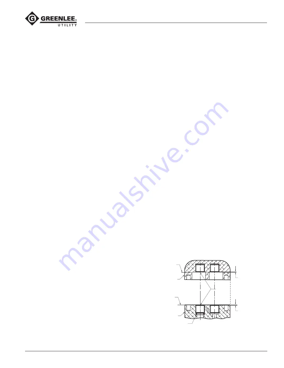
Needle Bearing Installation in Handle or Motor Cap
HANDLE:
1. Install a new needle bearing (3) with identification
mark facing up (readable from Surface A) into
the handle (1).
2. Press the bearing into the handle until the bearing
cage is 0.020 inch below Surface A.
3. Repeat the procedure for the other needle bearing if
it was removed.
MOTOR CAP:
1. Install a new needle bearing (48) with identification
mark facing up (readable from Surface B) into the
motor cap (47).
2. Press the bearing into the motor cap until the
bearing cage is 0.047 inch below Surface B.
3. Repeat the procedure for the other needle bearing if
it was removed.
Needle Bearing Installation
in Handle and Motor Cap
Surface B
Motor Cap
Surface A
Motor Body
O-ring Seal
Needle Bearing
0.020 below
Surface A
0.047 below
Surface B


