GreenJet – Centrifugal Jet Fan
6
®
BMS Communication & Speed Control
RS-485 Communication
MODBUS follows a simple master/slave model. Slave
devices perform data read/write requests which are
issued from a client device such as a PLC or building
management system. Assignable addresses for server
devices range from an address of 1 to theoretical
maximum of 247. For a complete address list or motor
control questions, please contact Ziehl Abegg support
center at 336-834-9339. Default communication
parameters for serial MODBUS communication can be
found below.
MODBUS Read Communication
Input Register Address
Full Parameter Name
Parameter Setting
14
Speed
Decimal value 0-65535 RPM
15
Motor Current
Decimal value 0-65535 (in 0.01 A steps)
21
Line Voltage
Decimal value 0-65535 (in 1 V steps)
25
Motor Temperature
Decimal value 0-65535 (in 0.1 degrees C steps)
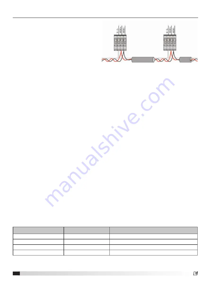
Figure 6 -
General example for MODBUS device
connection
Recommended Wire Types
1. CAT5 / CAT7 cables
2. J-Y (St) 2x2x0.6 (telephone wire)
3. AWG22 (2x2 twisted pair)
When using telephone flex with four cable cores, it is
recommended the following allocation:
“A (D+)” = red, “B (D-)” = black, “GND” = white
Pay attention to sufficient distance from power lines and
motor wires (min. 8 inches).
Max allowed wire length 3,280 feet (CAT5/7 500 m).
Networking via MODBUS-RTU
The device comes equipped with a RS-485 interface
for networking via MODBUS. Connection at: SI G-,
MDBS+1 and MDBS-1.
The address must be set in the IO Setup menu.
RS-485 - Network Design and Interface
Parameter
Ensure the correct connection; i.e. MDBS-1 must
always be connected to MDBS-1 of the next device.
The same applies to MD+1.
A “GND” connection must be established, as dissimilar
to potential (over 10V) will lead to the destruction of the
RS-485 interface (e.g. lightning).
Always use two wires of one lead (twisted pair) for
connection.
• COM Bus Address: 247
• COM Baud rate: 19200 Bd
• COM Mode: 8E1
• Bits = 8
• Parity = Even
• Stop bits = 1
• Handshake = None


