97
Installation and Maintenance
Service Manual
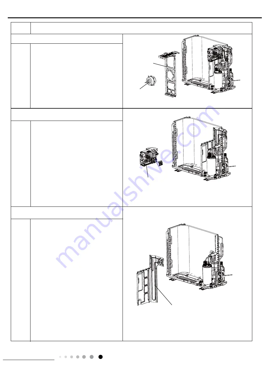
Remove the tapping screws fixing the
motor and disconnect the leading wire
insert of the motor. Then remove the
motor.
Remove the tapping screws fixing the
motor support and lift the motor support to
remove it.
Remove screws fixing the electric box
subassembly; loosen the wire bundle and
unplug the wiring terminals. Then lift the
electric box to remove it.
Remove the screws fixing the isolation
sheet and then remove the isolation
sheet.
motor support
motor
Electric Box Assy
Procedure
Steps
isolation sheet
8. Remove motor and motor support
9. Remove Electric Box Assy
10. Remove isolation sheet
Summary of Contents for GWH09AGA-K6DNA1A/I
Page 1: ...Service Manual Change for life GREE ELECTRIC APPLIANCES INC OF ZHUHAI...
Page 18: ...15 Technical Information Service Manual 841 912 309 373 349 582 646 Unit mm 24K...
Page 102: ...99 Installation and Maintenance Service Manual 18K...
Page 103: ...100 Installation and Maintenance Service Manual...
Page 104: ...101 Installation and Maintenance Service Manual...
Page 105: ...102 Installation and Maintenance Service Manual Capillary Sub assy...
Page 107: ...104 Installation and Maintenance Service Manual screws Rear Grill...
Page 108: ...105 Installation and Maintenance Service Manual...
Page 109: ...106 Installation and Maintenance Service Manual...
Page 110: ...107 Installation and Maintenance Service Manual...
Page 111: ...108 Installation and Maintenance Service Manual...


