background image

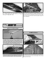
5. Drill a 1/16" [1.6mm] hole through the fuse at an angle

for the receiver antenna as shown. When drilling the hole, be
sure your drill is angled enough to prevent drilling into the
duct channel.

6. Feed the antenna through the hole to the underside of

the fuse. Use clear tape to secure the antenna to the
underside of the plane. Be sure that it does not interfere with
the elevons.

7. Finish the model by gluing the intake ring to the front

of the duct channel.

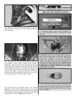
1. Turn on the transmitter and receiver and center the trims.

2. Activate the elevon function on your radio. If you are

unsure how to do this, consult your radio manual.

3. With the transmitter and receiver still on, check all the

control surfaces to see if they are centered. If necessary, adjust
the lengths of the pushrods within the heat-shrink tubing and
secure them again with CA glue.

4. Make certain that the control surfaces and the throttle

respond in the correct direction as shown in the diagram. If
any of the controls respond in the wrong direction, use the
servo reversing in the transmitter to reverse the servos
connected to those controls. Be certain the control surfaces
have remained centered. Adjust if necessary.

Use a Great Planes AccuThrow (or a ruler) to accurately
measure and set the control throw of each control surface as
indicated in the chart that follows. If your radio does not have
dual rates, we recommend setting the throws at the low
rate 
setting.

Note: The throws are measured at the widest part of
the elevons.

Set the Control Throws

Check the Control Directions

GET THE MODEL READY TO FLY

12

Summary of Contents for XPD-8

Page 1: ...s kit immediately in new and unused condition to the place of purchase To make a warranty claim send the defective part or item to Hobby Services at the address below Hobby Services 3002 N Apollo Dr S...

Page 2: ...EDF airplanes fan units and motors This is the first design of many to come for the Great Planes 370 EDF unit Build the airplane per the instructions and enjoy Note This model is also available with t...

Page 3: ...8 ARF that may require planning or decision making before starting to build Order numbers are provided in parentheses The XPD 8 ARF requires a transmitter that supports elevon mixing a micro receiver...

Page 4: ...heel GPMR8020 Servo horn drill HCAR0698 AccuThrow Deflection Gauge GPMR2405 CG Machine GPMR2400 Hobbico Flexible 18 Ruler Stainless Steel HCAR0460 When you see the term test fit in the instructions it...

Page 5: ...er Replacement Parts List GPMA1867 XPD 8 Flying Wing Only GPMA2748 Canopy XPD 8 GPMG0311 370 BB Brushed Motor GPMG3910 HyperFlow 370 EP DF w o Motor GPMG3911 HyperFlow 370 EP DF w Motor GPMG3940 Hyper...

Page 6: ...y are written in the Kit Contents list on this page Great Planes Product Support 3002 N Apollo Drive Suite 1 Champaign IL 61822 Telephone 217 398 8970 ext 5 Fax 217 398 7721 E mail airsupport greatpla...

Page 7: ...left on the underside of the fuse from the T pins can be connected with a drawn line for future reference If at any time you need to remove the fan unit use a hobby knife to cut along the holes left...

Page 8: ...ed 1 Measure back 7 3 8 187mm from the front of the duct channel top and make a mark on both sides of it as shown in the pictures above Install the Servos B Press the tube into the foam and twist The...

Page 9: ...are close to the center of the duct channel top as shown but not entering the duct channel 3 Cut off three arms from the four arm servo horns included with the servo and enlarge the outer hole with a...

Page 10: ...heat shrink tubing onto one of the pushrods Overlap the pushrod ends and join them together with the heat shrink tubing 10 While holding the elevons in the neutral position carefully use a soldering...

Page 11: ...ervo extension for one of the servo leads If you need to make a battery connector adapter to connect your LiPo battery pack to the ESC see the Expert Tip that follows C Cut a 3 8 9 5 mm long piece of...

Page 12: ...ol surfaces to see if they are centered If necessary adjust the lengths of the pushrods within the heat shrink tubing and secure them again with CA glue 4 Make certain that the control surfaces and th...

Page 13: ...r antenna collapsed and the receiver and transmitter on you should be able to walk at least 100 feet 30m away from the model and still have control Have an assistant stand by your model and while you...

Page 14: ...any pre existing flying site except in accordance with the frequency sharing agreement listed in the complete AMA Safety Code 9 Under no circumstances may a pilot or other person touch a powered mode...

Page 15: ...ltitude Continue to fly around executing turns and making mental notes or having your assistant take notes for you of what additional adjustments or C G changes may be required to fine tune the model...

Page 16: ...____________ Where Purchased _________________________ Date Construction Started __________________ Date Construction Finished _________________ Finished Weight __________________________ Date of Firs...

Reviews: