background image

3. I will perform my initial turn after takeoff away from the pit
or spectator areas and I will not thereafter fly over pit or
spectator areas, unless beyond my control.

4. I will operate my model using only radio control frequencies
currently allowed by the Federal Communications Commission.

1. Fuelproof all areas exposed to fuel or exhaust residue

such as the cowl ring, cowl mounting blocks, wing saddle
area, etc.

2. Check the C.G. according to the measurements

provided in the manual.

3. Be certain the battery and receiver are securely

mounted in the fuse. Simply stuffing them into place with
foam rubber is not sufficient.

4. Extend your receiver antenna and make sure it has a

strain relief inside the fuselage to keep tension off the solder
joint inside the receiver.

5. Balance your model 

laterally as explained in 

the instructions.

6. Use threadlocking compound to secure critical fasteners

such as the set screws that hold the wheel axles to the struts,
screws that hold the carburetor arm (if applicable), screw-lock
pushrod connectors, etc.

7. Add a drop of oil to the axles so the wheels will turn freely.

8. Make sure all hinges are securely glued in place.

9. Reinforce holes for wood screws with thin CA 

where appropriate (servo mounting screws, cowl mounting
screws, etc.).

10. Confirm that all controls operate in the correct

direction and the throws are set up according to the manual.

11. Make sure there are silicone retainers on all the

clevises and that all servo arms are secured to the servos
with the screws included with your radio.

12. Secure connections between servo wires and Y-

connectors or servo extensions and the connection between
your battery pack and the on/off switch with vinyl tape, heat
shrink tubing or special clips suitable for that purpose.

13. Make sure any servo extension cords you may have

used do not interfere with other systems (servo arms,
pushrods, etc.).

14. Secure the pressure tap (if used) to the muffler with high

temp RTV silicone, thread locking compound or J.B. Weld.

15. Make sure the fuel lines are connected and are 

not kinked.

16. Balance your propeller (and spare propellers).

17. Tighten the propeller nut and spinner.

18. Place your name, address, AMA number and

telephone number on or inside your model.

19. Cycle your receiver battery pack (if necessary) and

make sure it is fully charged.

20. If you wish to photograph your model, do so before

your first flight.

21. Range check your radio when you get to the flying field.

The U-Can-Do 3D .46 ARF is a great-flying model that flies
smoothly and predictably. The U-Can-Do 3D .46 ARF does
not, however, possess the self-recovery characteristics of a
primary R/C trainer and should be flown only by experienced
R/C pilots.

Whether you are looking to practice new 3D maneuvers and
don't want to risk your competition aircraft, or are just
starting to learn the most basic aerobatics, the U-Can-Do
3D .46 ARF is a great choice. Regardless of your skill level,
be sure your first flight begins with low rates (yes, even in a
crosswind) and that you gradually expand your flight, adding
one new maneuver at a time.

Take offs, landings and most of your normal flights should be
flown on low rates. (If your radio does not have dual rates, be
sure to set the model up on the low rates provided.) The high
rates on this model are meant ONLY for use when doing 3D
aerobatics – maneuvers performed while the model is flying
slower than its normal stall speed. That includes maneuvers
as simple as a stall turn, or as complex as harrier rolls.

Don't get spoiled by how incredibly well the U-Can-Do 3D
.46 ARF hangs and torque rolls! Most models take an
enormous amount of work to keep the model stationary in a
hanger, but the unique design of U-Can-Do 3D .46 ARF
helps lock it solid in position and torque roll and hang with
relative ease.

Fuel Mixture Adjustments
A fully cowled engine may run at a higher temperature than
an un-cowled engine. For this reason, the fuel mixture
should be richened so the engine runs at about 200 RPM
below peak speed. By running the engine slightly rich, you
will help prevent dead-stick landings caused by overheating.

FLYING

During the last few moments of preparation your mind
may be elsewhere anticipating the excitement of the first
flight. Because of this, you may be more likely to overlook
certain checks and procedures that should be performed
before the model is flown. To help avoid this, a checklist is
provided to make sure these important areas are not
overlooked. Many are covered in the instruction manual,
so where appropriate, refer to the manual for complete
instructions. Be sure to check the items off as they are
completed (that's why it's called a

check list!).

CHECK LIST

24

Summary of Contents for U-Can-Do 3D.46

Page 1: ...ser assembled product By the act of using the user assembled product the user accepts all resulting liability If the buyer is not prepared to accept the liability associated with the use of this produ...

Page 2: ...the U CAN DO 3D 46 ARF visit the web site listed below and select the Great Planes U CAN DO 3D 46 ARF If there is new technical information or changes to this model a tech notice box will appear in th...

Page 3: ...all bearing servos 50 in oz FUTM0220 If using a computerized radio two 24 servo extensions HCAM2200 If not using a computerized radio with Ailevator programming then a servo reversing harness is requi...

Page 4: ...CAR0667 Dead Center Engine Mount Hole Locator GPMR8130 Great Planes AccuThrow Deflection Gauge for measuring control throws GPMR2405 There are two types of screws used in this kit Sheet metal screws a...

Page 5: ...Cowl Canopy Wheel Pants 10 6 32x3 4 socket head cap screw Main Gear Engine Engine Mount 10 2 56x1 2 Socket head cap screw Rudder Elevator Ailerons 5 Faslink Rudder Elevator Ailerons 1 3 32 Wheel coll...

Page 6: ...Number Description How to Purchase Missing pieces Contact Product Support Instruction manual Download at greatplanes com Full size plans Not available Kit parts listed below Hobby Supplier GPMA2360 F...

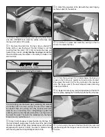
Page 7: ...the servo openings to thoroughly bond the covering to the wood 1 Trim the covering on the wing from A The servo wire hole in the top center of the wing B Both servo openings C Dowel hole D Top and Bot...

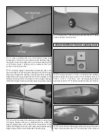
Page 8: ...fere with the free movement of the aileron 9 Stick a pin through the center of each hinge Fit the ailerons to the wing with the hinges The pin will keep the hinge centered Remove the pins from the hin...

Page 9: ...unt for the servo screws Add a few drops of thin CA to the holes and allow to fully harden Mount the aileron servo using the hardware that came with the servo 5 Make a mark on the bottom L E of the ri...

Page 10: ...orn Hold the aileron straight with the wing and mark the pushrod where it crosses the servo arm Bend the pushrod 90 degrees away from the wing on the mark you made 10 Attach the pushrod to the control...

Page 11: ...proceed to the next step If the stab and wing do not align place a weight on the high side of the stab to bring it into alignment If much weight is required remove the stab and sand the high side of...

Page 12: ...e faster it must move to melt a fine cut 8 Use 30 minute epoxy to glue the stab into the fuse For the most strength apply epoxy to both sides of the stab Slide the stab into position Wipe away residua...

Page 13: ...and wipe away any excess epoxy 16 Test fit the rudder to the tail gear and the fin using three CA hinges Repeat until you are satisfied that the rudder fits properly Apply epoxy in the rudder for the...

Page 14: ...wheel to the axle and tighten the set screw 6 With the plane on its wheels on a flat surface block the TE of the wheel pants 3 4 19mm off the surface 7 Drill two 1 16 1 6mm holes through the pant usi...

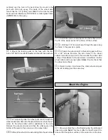
Page 15: ...s through the mount at the marks you made Tap 6 32 threads into the mount Mount the engine to the mount with four 6 32 x 3 4 19mm SHCS 6 flat washers and 6 lock washers 1 Use epoxy to glue the four 3...

Page 16: ...cluded with this kit Use epoxy to securely glue the filler valve mount to the firewall in a location where the filler valve will be accessible outside the cowl when it s time to fuel the engine 10 Use...

Page 17: ...certain the fuel line weight clunk at the end of the fuel line inside the tank does not contact the rear of the tank Otherwise the line may become stuck above the fuel level and discontinue fuel flow...

Page 18: ...came with the servo 4 Make a mark on the top L E of each elevator 5 8 15 9mm from the inboard edge of each elevator Position the control horn centered over the mark Mark the hole locations on the elev...

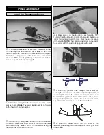
Page 19: ...ushrods where they cross the servo arms Bend the pushrods 90 degrees away from the fuse on the marks you made Turn the receiver and transmitter off 11 Using Faslinks attach the pushrods to the control...

Page 20: ...32 2 4mm hole through the bottom sheeting aft of the wing opening and routed the antenna through the hole The end of the antenna was connected to a hook made from a cut off servo arm connected to a sm...

Page 21: ...NOTE The throws are measured at the widest part of the elevators rudder and ailerons At this stage the model should be in ready to fly condition with all of the systems in place including the engine l...

Page 22: ...model it means that side is heavy Balance the airplane by adding weight to the other wing tip An airplane that has been laterally balanced will track better in loops and other maneuvers No matter if y...

Page 23: ...ket pockets into the prop Use a chicken stick or electric starter to start the engine Do not use your fingers to flip the propeller Make certain the glow plug clip or connector is secure so that it wi...

Page 24: ...9 Cycle your receiver battery pack if necessary and make sure it is fully charged 20 If you wish to photograph your model do so before your first flight 21 Range check your radio when you get to the f...

Page 25: ...ed by keeping the nose down as you turn onto the crosswind leg Make your final turn toward the runway into the wind keeping the nose down to maintain airspeed and control Level the attitude when the m...

Page 26: ...ger engine Using a larger engine than recommended will put your model at high risk for catastrophic failure and void any protections offered in its warranty Spinner 2 True Turn TRUQ1060 and True Turn...

Page 27: ...t reduces weight for smoother faster response Dual bearings in the final gear speed transit time Comes with J connector one attached servo horn three extra servo horns and mounting hardware 1 year war...

Page 28: ...____________ Where Purchased _________________________ Date Construction Started __________________ Date Construction Finished _________________ Finished Weight __________________________ Date of Firs...

Reviews: