background image

3. I will perform my initial turn after takeoff away from the pit
or spectator areas and I will not thereafter fly over pit or
spectator areas, unless beyond my control.

4. I will operate my model using only radio control
frequencies currently allowed by the Federal
Communications Commission...

During the last few moments of preparation your mind may
be elsewhere anticipating the excitement of the first flight.
Because of this, you may be more likely to overlook certain
checks and procedures that should be performed before the
model is flown. To help avoid this, a checklist is provided to
make sure these important areas are not overlooked. Many
are covered in the instruction manual, so where appropriate,
refer to the manual for complete instructions. Be sure to
check the items as off they are completed (that's why it's
called a 

check list!).

1. Fuelproof all areas exposed to fuel or exhaust residue

such as the cowl mounting blocks, wing saddle area, etc.

2. Check the C.G. according to the measurements

provided in the manual.

3. Be certain the battery and receiver are securely

mounted in the fuse. Simply stuffing them into place
with foam rubber is not sufficient.

4. Extend your receiver antenna and make sure it has a

strain relief inside the fuselage to keep tension off the
solder joint inside the receiver.

5. Balance your model laterally as explained in 

the instructions.

6. Use thread locking compound to secure critical

fasteners such as the set screws that hold the wheel
axles to the struts, screws that hold the carburetor arm
(if applicable), screw-lock pushrod connectors, etc.

7. Add a drop of oil to the axles so the wheels will turn freely.

8. Make sure all hinges are 

securely

glued in place.

9. Reinforce holes for wood screws with thin CA where

appropriate (servo mounting screws, cowl mounting 
screws, etc.).

10. Confirm that all controls operate in the correct direction

and the throws are set up according to the manual.

11. Make sure there are silicone retainers on all the

clevises and that all servo arms are secured to the
servos with the screws included with your radio.

12. Secure connections between servo wires and Y-

connectors or servo extensions and the connection
between your battery pack and the on/off switch with
vinyl tape, heat shrink tubing or special clips suitable
for that purpose.

13. Make sure any servo extension cords you may have

used do not interfere with other systems (servo arms,
pushrods, etc.).

14. Secure the pressure tap (if used) to the muffler with

high temp RTV silicone, thread locking compound or
J.B. Weld.

15. Make sure the fuel lines are connected and are not

kinked.

16. Use an incidence meter to check the wings for twists

and attempt to correct before flying.

17. Balance your propeller (and spare propellers).

18. Tighten the propeller nut and spinner.

19. Place your name, address, AMA number and

telephone number on or inside your model.

20. Cycle your receiver battery pack (if necessary) and

make sure it is fully charged.

21. If you wish to photograph your model, do so before

your first flight.

22. Range check your radio when you get to the flying

field. Perform the range check with the engine
running and without the engine running.

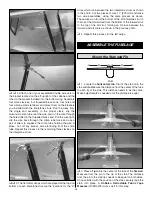
The Tiger Moth is a great-flying model that flies
smoothly and predictably. The Tiger Moth does not,
however, possess the self-recovery characteristics of a
primary R/C trainer and should be flown only by
experienced R/C pilots.

A fully cowled engine may run at a higher temperature than
an un-cowled engine. For this reason, the fuel mixture
should be richened so the engine runs at about 200 rpm
below peak speed. By running the engine slightly rich, you
will help prevent dead-stick landings caused by overheating.

CAUTION:

If, while flying, you notice any unusual sounds,

such as a low-pitched “buzz,” this may indicate control
surface 

flutter. Because flutter can quickly destroy

components of your airplane, any time you detect flutter
you must 

immediately

cut the throttle and land the

airplane! Check all servo grommets for deterioration (this
may indicate which surface fluttered) and make sure all
pushrod linkages are secure and free of play. If the control
surface fluttered once, it probably will flutter again under
similar circumstances unless you can eliminate the free-
play or flexing in the linkages. Here are some things which
can cause flutter: Excessive hinge gap; Not mounting
control horns solidly; Poor fit of clevis pin in horn; Side-
play of pushrod in guide tube caused by tight bends; Poor
fit of Z-bend in servo arm; Insufficient glue used when
gluing in the elevator joiner wire; Excessive 

play or

backlash in servo gears; and Insecure servo mounting.

Fuel Mixture Adjustments

FLYING

CHECK LIST

24

Summary of Contents for Tiger Moth ARF

Page 1: ...ed product By the act of using the user assembled product the user accepts all resulting liability If the buyer is not prepared to accept the liability associated with the use of this product the buye...

Page 2: ...to serve the post war RAF until 1951 There are more than 250 still flying today The Tiger Moth has a wingspan of 29 ft 4 in a fuse length of 23 ft 11 in and is powered by a 145 hp deHavilland Gipsy Ma...

Page 3: ...AA events The IMAA International Miniature Aircraft Association is an organization that promotes non competitive flying of giant scale models If you plan to attend an IMAA event contact the IMAA for a...

Page 4: ...1 4 drill bit set Curved Tip Canopy Scissors for Trimming Plastic Parts HCAR0667 Dead Center Engine Mount Hole Locator GPMR8130 Great Planes Receiver Guard GPMM1010 Great Planes AccuThrow Deflection...

Page 5: ...parts contact Great Planes Product Support Replacement Parts List Order Number Description How to Purchase Missing pieces Contact Product Support Instruction manual Contact Product Support Full size p...

Page 6: ...4 Black Spinner 2 1 4 20 Blind nuts pre installed in wing hold down plate 4 4 x 18mm Wood screws cabanes to fuse 18 3 x 12mm Wood screws brackets for struts and wires 4 2 5 x 8mm Wood screws cowl to f...

Page 7: ...Bottom Wing and ailerons 3 Cut fourteen 3 4 x 1 19mm x 25mm hinges from the CA hinge strip Snip off the corners as shown so they go in easier Insert three of the hinges into the aileron hinge slots 4...

Page 8: ...o arm hole at 90 degrees from the aft edge of the aileron bay At this location mark and drill the two 1 16 1 6mm holes into the bottom of the aileron for mounting the nylon control horn Saturate the h...

Page 9: ...re in full contact and that the leading and trailing edges align Proceed to the next step immediately The following sketch shows how the lower wing dihedral is measured 5 Check for the correct dihedra...

Page 10: ...e top of the bottom wing and install the four compound bend metal brackets in place Install two 45 degree metal brackets in the pre drilled holes near the center of the wing with 3mm x 12mm wood screw...

Page 11: ...ay loosen the screws holding the center section to the cabane struts make minor adjustments and re tighten the screws 18 Use 30 minute epoxy to thoroughly coat the root rib of the right wing half the...

Page 12: ...cations for the X wires which run between the two interplane struts as shown in the photo Cut two pieces of wire 11 279mm and make two wire assemblies using the same process as above These wires run f...

Page 13: ...el 6 After the epoxy has cured remove the MonoKote covering from the section where the fin fits into the horizontal stab and just forward and aft of the opening being careful not to cut into the wood...

Page 14: ...e bottom of the rudder Also mark the location of the nylon bearing and cut a slot for it in the aft end of the fuse with a 11 blade 13 Drill a 3 32 2 4mm hole in the rudder at the marked location to t...

Page 15: ...ing bolts 4 Temporarily secure the engine to the mount with the back plate of the spinner 5 3 4 146mm from the firewall A Great Planes Dead Center Engine Mount Hole Locator GPMR8130 works well to mark...

Page 16: ...through the hole in the firewall Be certain the vent tube inside the tank is pointing upward Glue the tank into place with epoxy or silicone 3 In order to mount the optional Great Planes Easy Fueler...

Page 17: ...holes through the rudder and harden the area with CA Mount the horn with 2 56 x 3 4 19mm socket head cap screws and the nylon mounting plate on the other side of the control horn 5 Install the rubber...

Page 18: ...ou may find it easier to install your receiver battery pack and switch harness before installing the throttle linkage 15 Installation of the receiver can be done using a Great Planes Receiver Guard GP...

Page 19: ...make them with a slot in order fit them properly Glue the tube into place with epoxy at both braces and at the firewall 21 Set the carburetor to the closed position Turn the radio system on and move t...

Page 20: ...ft balsa sheet or something similar to squeegee the rest of the water from under the decal Allow to dry overnight before flying the model 2 On our model we placed a black trim stripe cut from a black...

Page 21: ...ed for takeoff and make it more difficult to slow for landing Moving the C G aft makes the model more maneuverable but could also cause it to become too difficult for you to control In any case start...

Page 22: ...s 2 If one wing always drops when you lift the model it means that side is heavy Balance the airplane by adding weight to the other wing tip An airplane that has been laterally balanced will track bet...

Page 23: ...or electric starter to start the engine Do not use your fingers to flip the propeller Make certain the glow plug clip or connector is secure so that it will not pop off or otherwise get into the runn...

Page 24: ...nyl tape heat shrink tubing or special clips suitable for that purpose 13 Make sure any servo extension cords you may have used do not interfere with other systems servo arms pushrods etc 14 Secure th...

Page 25: ...maneuvers and making mental notes or having your assistant write them down of what trim or C G changes may be required to fine tune the model so it flies the way you like Mind your fuel level but use...

Page 26: ...maneuvers GPMA1340 Wingspan 70 in Wing Area 770 sq in Weight 8 lb Wing Loading 24 oz sq ft Length 55 in Requires 2 stroke 61 75 or 4 stroke 91 engine 4 7 channel radio w 5 7 servos The first ARF of t...

Page 27: ...erior compression and improved output in the power stroke It easily swings large props and supplies more usable horsepower for quick takeoffs and acceleration and virtually unlimited vertical performa...

Page 28: ...____________ Where Purchased _________________________ Date Construction Started __________________ Date Construction Finished _________________ Finished Weight __________________________ Date of Firs...

Reviews: