10
❏
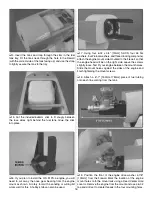
2. Test fi t the
horizontal stabilizer
into the stab slot at
the aft end of the fuselage (without glue). Center the stab left
and right in the fuse. Measure the distance from the stab tips
to the wing tips and make the measurements equal. Now,
stand behind the model approximately 5-6 ft [1.5-1.8m] and
confi rm that the stab and wings are parallel. If not, weight
can be added to one side to bring them parallel, or the stab
can be taped to the fi n to pull it parallel with the wing.
❏
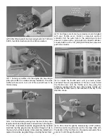
3. After you have determined if any weight will need to
be added during the gluing process, remove the stab from
the fuse. If necessary, lightly sand away any excess paint
from inside the stab slot. Mix up a batch of 30-minute epoxy
and coat the stab slot as well as the exposed wood of the
stabilizer (coating the stab slot will require additional cleanup
after inserting the stab into the fuse. However, it will make a
stronger glue joint). Slide the stab into the fuse, center it left
and right and align it with the wing panels. Use denatured
alcohol to clean up any excess epoxy. Allow the epoxy to
cure undisturbed.
❏
4. When the epoxy has cured, the wing panels can be
removed from the fuselage and set aside. They will not be
needed again until it is time to set up the control throws.
1"
1"
3/4"
❏
5. Cut the included 2" x 9" [51mm x 229mm] CA hinge
strip into 3/4" x 1" [19mm x 25mm] individual hinges. Clip the
corners of each hinge to make them easier to insert into the
hinge slots.
DRILL A 3/32" HOLE,
1/2" DEEP, IN CENTER
OF HINGE SLOT
❏
6. Drill a 3/32" [2.4mm] hole 1/2" [13mm] deep into the
center of each hinge slot in the stab and
elevator halves
.
❏
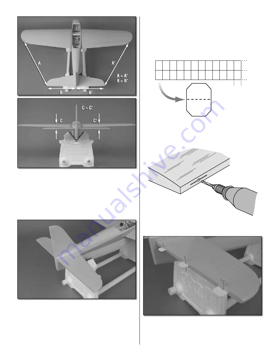
7. Test fi t a CA hinge into each of the hinge slots in the
stab and elevator halves. If necessary, enlarge the slots with
a hobby knife. When satisfi ed with the fi t, insert a CA hinge
halfway into each hinge slot in the wing panel. Push a pin
through the middle of each hinge to keep them centered.


