22
❏
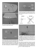
6. Install the canopy hatch onto the fuselage by fi tting the
dowels into the receiving holes, pressing the tabs at the aft
end of the hatch into the slots, and then sliding the hatch
back. Apply pieces of masking tape in the locations shown.
Mark the locations for the cowl mounting screw holes on the
tape using the measurements shown in the pictures. In order
to transfer the mounting hole locations onto the cowl, draw
a 3-3/4" [95mm] line along the tape pieces, starting the lines
at your marks.
❏
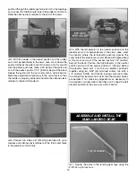
7. Before fi tting the cowl, make any cutouts necessary
for your power system. If you are installing a glow engine, a
cutout must be made for the engine head, exhaust outlets,
clearance for the throttle clevis, and needle valve access. A
1/4" [6.4mm] hole can be drilled or reamed into the cowl for
convenient fi ll line access. The fuel tubing will slide through
the hole, but the included fuel line plug will fi t snugly into the
hole, holding it securely in place during fl ight. If you have
installed a brushless power system, make a cooling hole
cutout near the bottom aft edge of the cowl. Templates for
cooling hole cutouts are provided in the back of this manual
if you have installed a brushless system.
❏
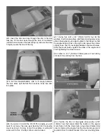
8. If necessary, ream the spinner backplate to match the
diameter of the prop shaft. Fit the cowl onto the fuselage
and slide the spinner backplate onto the prop shaft. Position
the cowl so that the front of it is centered with the spinner
backplate and is 3/32" [2.4mm] behind it. Temporarily tape
the cowl into place or have a helper hold it steady while you
transfer the cowl mounting hole locations onto the cowl. Do
this by measuring forward along the lines on the tape 3-3/4"
[95mm] and marking on the cowl for the fi ve screw holes.
❏
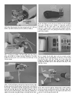
9. Drill 5/64" [2mm] holes at the marks you made on the
cowl
through the cowl mounting blocks
that are pre-glued
inside the fuselage. Remove the cowl and thread a #4 x 1/2"

