D 6. Temporarily mount the control horns on the
rudder and elevator. (Note that the elevator horn is
mounted on the bottom, and the rudder horn is
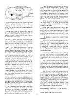
mounted on the left side.) To do this, insert two 2-56
screws through the holes in the horn and through
the holes you drilled. Then screw them into the nylon
"nutplate" which originally came attached to the
horn.
D 7. Re-install the rudder and elevator onto the fin
and stab, but do not glue in the hinges.
PUSHRODS
D 1. Get the following parts together before start-
ing:
2- 1/4" diameter hardwood dowels, 25" long
6- 12" long wire, threaded one end
2- small nylon aileron clevis connector
2-
n y l o n a i l e r o n c l e v i s
4- standard nylon clevis
10 feet of kite string or strong thread (not
supplied)
D 2. Write "elevator pushrod" on one of the 1/4" x
25" dowels, and "rudder pushrod" on the other.
D 3. Lay the elevator pushrod dowel on the fuselage
top view. Note that the front pushrod wire attaches
to the top of this dowel, and the rear wire attaches
to the right side. To avoid confusion later, draw lines
l-3/8"long on the dowel where the wires will be at-
tached.
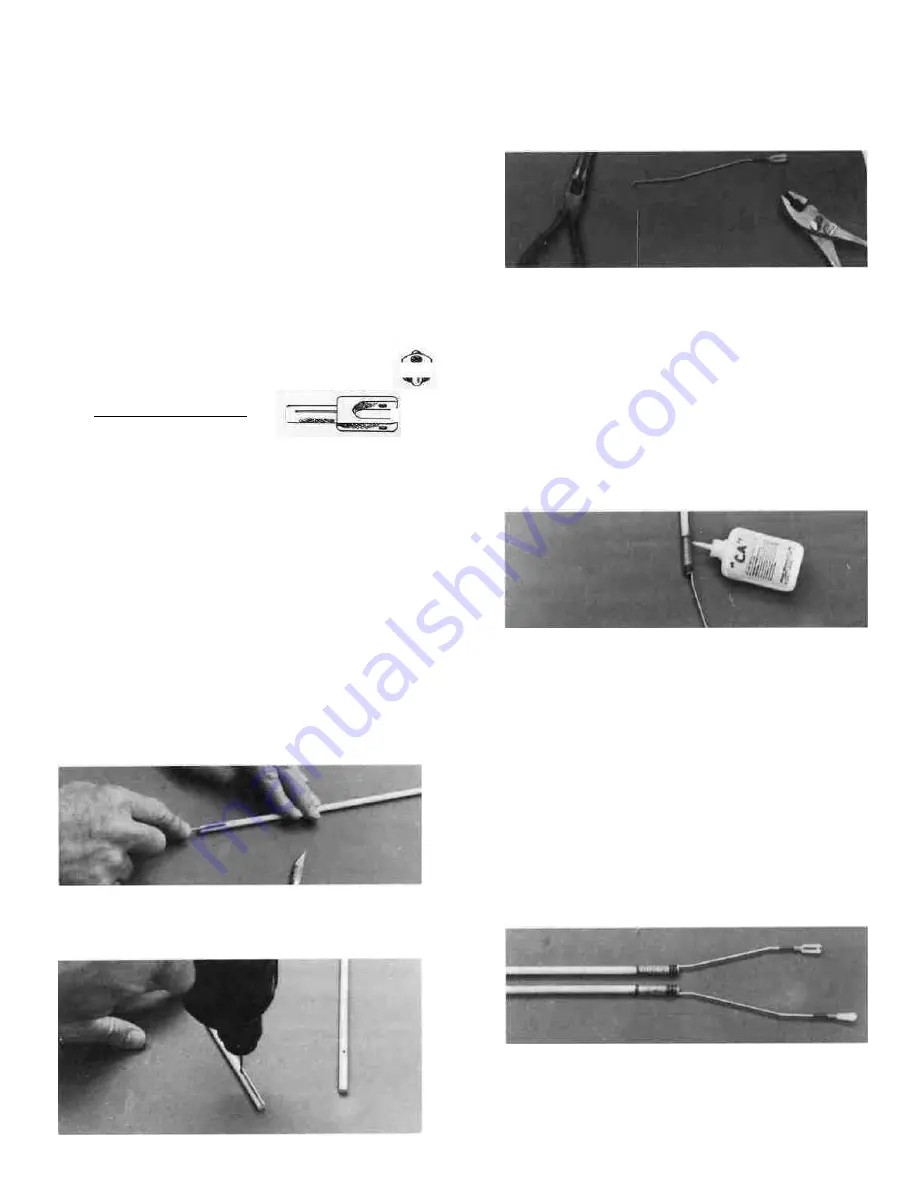
D 4. Use the threaded end of one of the wire push-
rods to "file" grooves in the dowel where you drew
the lines. The grooves need not be deeper than 1/2
the thickness of the wire.
D 5. Drill 5/64" holes through the dowel, 1-3/8" in
from each end, at the end of the grooves you made
in step 4.
D 6. Take one of the 12" threaded wires, attach a
clevis and bend the wire to match the drawing of the
elevator rear pushrod wire (top view). At the front
end of this wire drawing, note that the wire makes
a 90 degree bend and goes into the dowel. Make this
bend now, and cut the wire off.
D 7. Round both ends of the dowel slightly to help
prevent the possibility of it "hanging up" on some-
thing.
D 8. With 100 grit sandpaper, roughen the end of
the wire that will be glued to the dowel.
D 9. Insert the wire into the hole and the groove
in the dowel. Apply a couple drops of thin CA to hold
in place.
D 10. Wrap kite string or strong thread around the
wire and dowel as shown on the plan, then apply
thick CA onto the string.
D 11. After cutting the pushrod wire to length in
step 6, you should have a straight piece of wire re-
maining that has a length of about 6-1/2 inches. Make
a short 90 degree bend in one end of this rod.
D 12. Roughen the end of the rod near the bent end
using sandpaper.
D 13. Insert this rod into the hole and groove in the
front end of the elevator pushrod dowel, wrap with
thread and apply thick CA.
D 14. Following a similar method as given in steps
3-13, make the "Rudder Pushrod". Note that the
groove in the front of the rudder pushrod is on the
top of the dowel while the groove in the rear is on
the left.
D 15. Remove the nylon clevises from the rear ends
of the elevator and rudder pushrods.
D 16. Insert the pushrods into the fuselage through
the openings in Formers 3-6 and out through the
slots in the fuse sides that you previously cut.
26


