background image

GLOSSARY

AILERON: The hinged, movable surfaces on the trailing edge of the wing
that causes the aircraft to roll (bank) left or right.

BREAKAWAY PLATE: A part, usually hardwood, to which the engine is
fastened by screws. The plate will "breakaway" in the event of a crash,

thereby saving the engine from damage.

BULKHEAD: A part that gives shape to the fuselage and also divides it into
different compartments. Same as a former. Usually designated "Fl", "F-
2",etc.

CA (CYANOACRYLATE): A glue that cures almost instantly to give a
strong bond. Thin CA seeps into a joint to bond it and thick CA will fill gaps
at a joint.

CLEARANCE HOLE: A hole drilled or cut in a part to leave room for
another part (screw, etc.) to fit through it.

CONTROL SURFACE: The movable parts of the aircraft that control its
operation: The rudder, the elevator, and the ailerons (some planes even
have flaps and/or spoilers).

DIHEDRAL: The angle between the right and left wing panels.

DIHEDRAL BRACE: An angled part that helps to hold the wing panels at
the correct angle, and provide strength in the center of the wing.

ELEVATOR: The hinged, movable part at the rear of the stabilizer that
causes the aircraft to climb or dive.

ENGINE BEAM: A part, usually hardwood or plywood, rigidly mounted
to the fuselage that supports the engine.

EPOXY: A two part glue consisting of a "resin" and a "hardener" that
when mixed together gives a very strong glue joint. Epoxy comes in
different bonding times: 5 minute, 15 minute, 30 minute, etc.

FINAL SAND: To use a fine grade of sandpaper to sand the airplane, after
everything is built, to get it ready to be covered or painted.

FIN: The vertical stabilizer or fixed part of the tail section that helps keep
the aircraft going straight ahead.

FIREWALL: A part, usually plywood, that separates the engine compart-
ment from the tank compartment. The engine mount or beams
are attached to the firewall.

FORMER: A part that gives shape to the fuselage and also divides it into
different compartments. Same as a bulkhead. Usually designated "F1",

"F-2", etc.

FUSELAGE (FUSE): The body of the model.

GLUE JOINTS: The area where two or more parts are joined together by
glue.

LEADING EDGE (L.E.): The front or forward edge of a part such as the
leading edge of the wing or the leading edge of the rudder.

PILOT HOLE: A small hole that is drilled to guide a screw into the wood.
The hole is smaller than the screw diameter.

RUDDER: The hinged, moveable part at the rear of the fin that causes the
aircraft to turn left or right

SADDLE: The areas on the fuselage where the wing and the stabilizer rests.

SPAR: A part that runs the length of the wing and acts to strengthen it.

STABILIZER (STAB): The fixed horizontal part of the tail section that
helps to keep the aircraft from pitching (climbing or diving).

TACK GLUE: To glue parts together temporarily so they will stay in place
during another procedure. A very small amount of glue is used so the parts
can be broken apart later.

TACK RAG: A chemically treated rag that is used to clean dust and dirt
from the model after it has been final sanded.

TRAILING EDGE (T.E.): The rear or back edge of a part such as the
trailing edge of the wing or the trailing edge of the rudder.

TRAIL PIT: The attempt to fit parts together before you glue them to make
sure they fit correctly..

WING PLATE: A piece of thin plywood that is glued to the top of the wing
to protect it from rubber bands or wing bolts.

WING: The part of the model that creates lift. The wing can be mounted
on top of the fuselage, on the bottom of the fuselage or somewhere in
between.

NOTICE:

Add shear webs to the wing as described below (after step 17 on page 18)

We have included in this kit, ten 3/32"

Balsa Shear Webs which are wrapped in clear
plastic. We recommend that you add them as

described below as they will add strength to the
wing which will help it survive violent manuev-
ers and crashes.

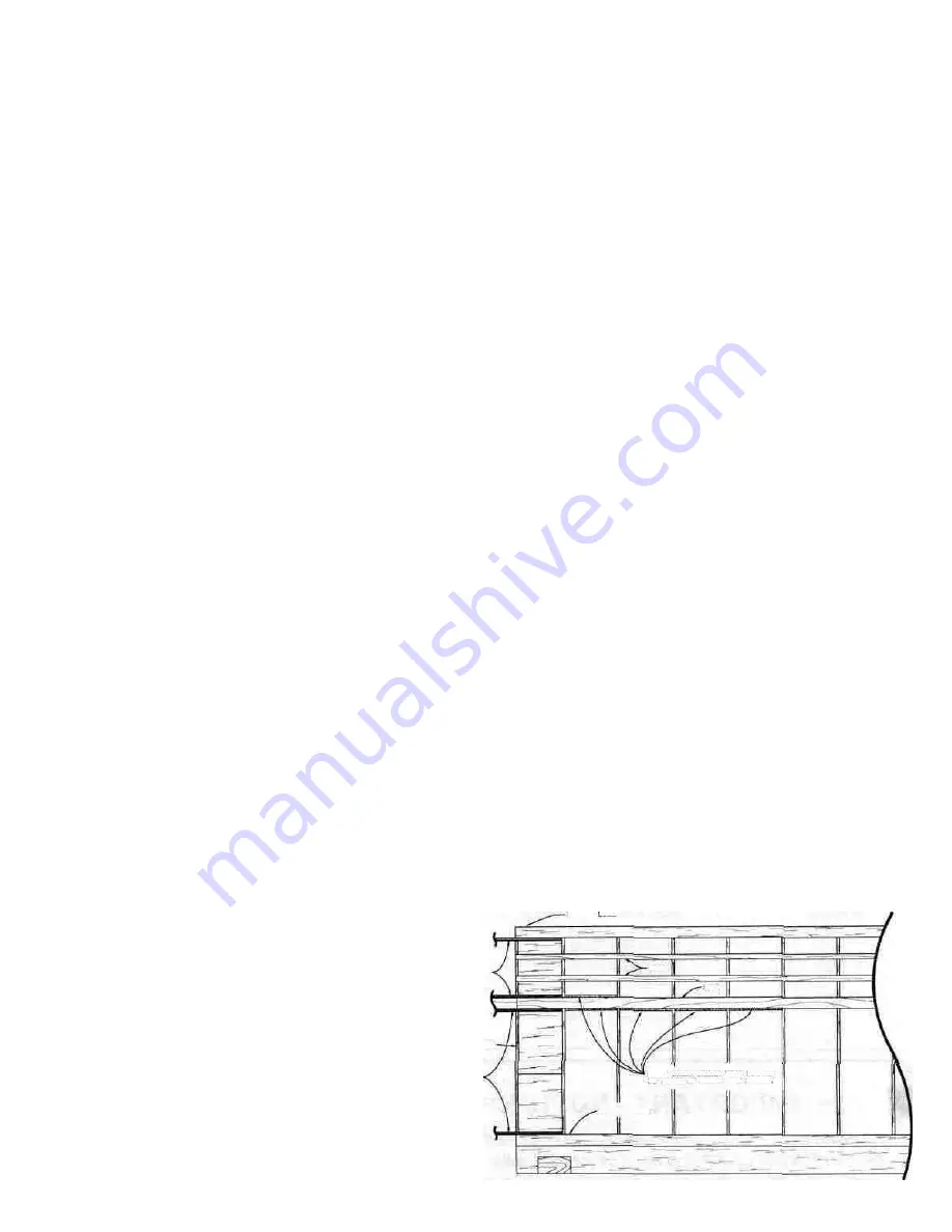
Glue a 3/32" balsa shear web to the

back side of the main 3/8" x 1/2" basswood spars
in each of the four rib bays shown in the sketch.

Also glue one shear web onto the front side of the
spars in the rib bay next to the dihedral brace.
These shear webs should be securely glued to the
spars for maximum strength and sanded flush
with the top and the bottom of the wing.

DIHEDRAL BRACES

WING ROOT (CENTER)

DIHEDRAL BRACES

3/32" BALSA SHEAR WEBS SHOULD
BE ADDED IN THESE FIVE PLACES

SPAR

SPAR

TRAILING EDGE

LEADING EDGE

39

Summary of Contents for PT-40

Page 1: ...components and flying gear engine tank pushrods etc and to test the model and fly it only with experi enced competent help in accordance with all safety standards and common sense as set down in the A...

Page 2: ...22 MOUNT THE ENGINE 23 INSTALL THE SERVOS 24 INSTALL NYLON CONTROL HORNS 25 PUSHRODS 26 BALANCE THE AIRPLANE LATERALLY 29 ADD THE FUSELAGE TOP 29 SAND THE FUSELAGE 30 FUELPROOF THE ENGINE AND FUEL TAN...

Page 3: ...t of the plans you are working on to prevent glues from sticking to the plans Remember a careful builder will build a warp free straight model that will fly as it was designed to Read and obey caution...

Page 4: ...217 398 8970 and we ll be glad to help It is a good idea to obtain the following items before you start building as you will need to install or test fit some of them before assembly is complete Most o...

Page 5: ...F WOOD HARDWARE TAPERED AILERON AND TRAILING EDGE STOCK 4 x 5 8 SCREW 2 x 3 8 S C R E W 4 40x1 BOLT 5 32 COLLAR AILERON CLEVIS 4x1 2 SCREW 6 32x3 16 SCREW 2 56 x 3 8 SCREW AILERON CLEVIS CONNECTOR PT4...

Page 6: ...terns shown here DIE CUT PARTS PATTERNS PT40W07 13 PER KIT WING RIBS 3 32x 3x12 BALSA PT40F07 I PER KIT 1 8 x 3 7 8 x 12 3 4 PLY FUSELAGE BOTTOM C3 SERVO TRAY PT40FIO 2 PER KIT 1 8 x 3 7 8 x 13 1 2 PL...

Page 7: ...as shown Press lightly to avoid damaging the balsa D 8 Now draw lines on the left inside fuse side using the edge marks and a straight edge D 6 Remove the fuse side from the plan and make small marks...

Page 8: ...triplers to the left inside fuselage side Be sure to follow the same procedure as set forth in steps 9 16 when doing so but don t make two Rt fuse sides D 18 Drill or cut out the 5 16 holes in the fus...

Page 9: ...slide two 62 rubber bands over the nose leav ing one around F l and one around F 2 Note Notice that the fuselage has now become somewhat rigid and square Before proceeding make sure that the tabs in...

Page 10: ...B saddles D 18 Check your assembly of the fuselage making sure that all former tabs are in their respective notches and all parts are in place Set the fuselage assembly on the plan top view Your fuse...

Page 11: ...is is the centerline of the three hatch hold down screws D 11 Holding the hatch firmly in position drill three 1 16 holes along the guideline D 12 Remove the hatch and re drill the holes in the hatch...

Page 12: ...e gear steering arm which consists of a nylon arm a 5 32 wheel collar and a 6 32 x 3 16 screw D 3 Place the steering arm assembly into the nose gear bracket making sure that the wheel collar open ing...

Page 13: ...and glue them to the ends of the elevator using thin CA glue Sand the ends even with the elevator using a sanding block D 4 Take the two remaining pieces of 1 4 x 1 4 balsa and glue them to the ends...

Page 14: ...S D 1 Lay the stab on the plan and mark the hinge locations on the stab trailing edge both sides are the same D 3 Repeat the above process marking the hinge locations on the fin and rudder Don t forge...

Page 15: ...and line up the fuse centerline which you previously drew on top ofthe stab with the mark on F 6 and with the center joint at the rear of the fuse D Check the squareness of the stab by measuring from...

Page 16: ...of next column D 8 Now temporarily assemble the elevator to the stab and the rudder to the fin Swing the rudder from side to side and the elevator up and down The rudder and elevator must not touch in...

Page 17: ...to get them close to their proper position DO NOT PUT A RIB AT THE CENTER LINE D 6 Insert the fronts of the ribs into the notches in the balsa leading edge L E D 7 Insert the backs of the ribs into t...

Page 18: ...excess glue with a tissue NOTE Skip to page 39 and add the shear webs as described on that page 18 Clamp or hold the parts until the glue hardens Set the right wing panel aside and turn the plan arou...

Page 19: ...If there are any major gaps between parts fill them with balsa dust from sanding and apply thin CA D 8 Sand the bottom of the center section smooth with a sanding block and 100 grit sandpaper At this...

Page 20: ...iece over a small table saw with the blade set at the height needed to cut a groove 5 32 deep D Rout the groove out with a Dremel Moto Tool and a 1 8 bit D 7 Turn the two inboard T E pieces upside dow...

Page 21: ...leading edge of each aileron to accept the torque rods D 21 Trial fit the ailerons onto the torque rods D 22 Cut or sand a small amount off both ends of the ailerons to provide about 1 16 to 3 32 of...

Page 22: ...4 Put the wing plates in position on the T E The edge of the plate that is not feathered goes to the rear along the trailing edge The 1 marks you made in step 3 are where the plates begin D 5 Apply th...

Page 23: ...he breakaway plates have also been cut out so your en gine can fit down between them If not do so now D 2 Put the engine in place on the breakaway plates Mark the area of the fuse side that must be cu...

Page 24: ...reversing instead they include one or two reverse or left handed servos which rotate in a direction opposite that ofthe other servos When installing the servos from a system that does not have servo...

Page 25: ...oles at these marks D 11 Attach a large servo wheel to your 4th servo D 12 Determine from the plan See the Bottom of Wing detail exactly where this aileron servo mount should be located Lay the mount...

Page 26: ...n step 4 D 6 Take one of the 12 threaded wires attach a clevis and bend the wire to match the drawing of the elevator rear pushrod wire top view At the front end of this wire drawing note that the wir...

Page 27: ...elevatorandrudderpushrodsfrom the fuselage and make Z bends in the pushrods at the marks you just made Here s how A Bend down with pliers D 24 Now you may re install the pushrods and in sert the Z ben...

Page 28: ...ss wire Note To re insertthe throttlepushrod youwill have to remove the clevis and slide the pushrod in from the rear Do so now D 35 Turn on the radio and check the operation of the throttle With the...

Page 29: ...the manual Now that you have the basic airframe nearly completed this is a good time to balance the airplane laterally side to side Here is how to do it D 1 Temporarily insert the wing hold down dowel...

Page 30: ...are of the tools you ll need to borrow or buy to apply the covering to the model The covering itself has an adhesive on the side that goes toward the wood The covering is heated so it will stick to th...

Page 31: ...ading edge D 13 Next cover the top of one of the wing panels At the center of the wing allow the covering to over lap the center ribs by about 1 2 Slit the covering at the spars then iron it down to t...

Page 32: ...push the elevator hinges into the slots Wipe away all excess epoxy with a tissue Re peat this process for the rudder D 4 Wing B only Glue the aileron hinges in place in the same manner but also apply...

Page 33: ...fuel pick up klunk through the hole in F l to the fit ting on the carburetor Run a second piece of tubing from the tank vent through the hole in F l to the pressure tap fitting on the muffler To prev...

Page 34: ...please ask an experienced model builder for assistance BALANCE YOUR MODEL NOTE THIS STEP IS VERY IMPORTANT AND MUST NOT BE OMITTED D 1 With the wing rubber banded to the fuselage all parts of the mod...

Page 35: ...ctions that come with the engine will tell you how to break in the engine ENGINE SAFETY PRECAUTIONS Note Failure to follow these safety precautions may result in severe injury to yourself and others K...

Page 36: ...similar and practice going around the cans without knocking them over 6 YOUR FIRST FLIGHT The ideal way to leam to fly is to use the buddy box system The instructor has his or her transmitter attache...

Page 37: ...t even though the pattern you flew may not have been per fect and the plane didn t do what you wanted it to do Hopefully you got the model down in one piece Turn off the transmitter and then the recei...

Page 38: ...ing hold down rubber bands may allow the wing to lift when making a tight turn or when pulling out of a dive 3 If the model is balanced more than 1 4 behind the recommended location it will be too pit...

Page 39: ...ea where two or more parts are joined together by glue LEADING EDGE L E The front or forward edge of a part such as the leading edge of the wing or the leading edge of the rudder PILOT HOLE A small ho...

Page 40: ...9 PT40F11 PT40F12 PT40F18 PT40R04 PT40S04 PT40W11 PT40M02 NYLON26 RUBB001 WBNT111 WIRES16 PT40M01 NUTS001 NYLON02 NYLON16 NYLON17 NYLON20 NYLON21 NYLON30 NYLON33 SCRW002 SCRW003 SCRW004 SCRW010 SCRW02...

Reviews: