24
❏
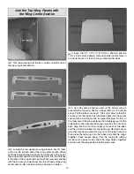
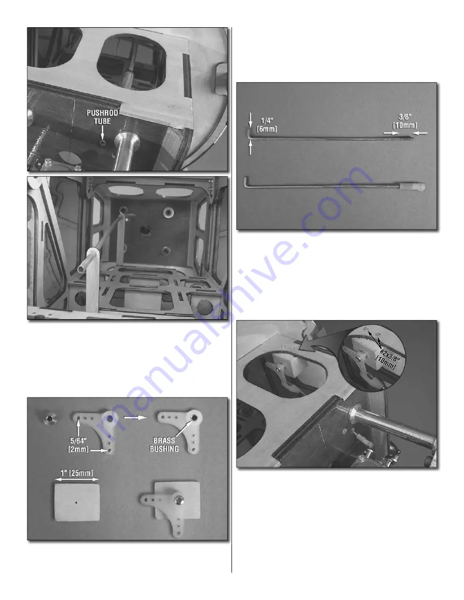
7. Cut the white
plastic throttle pushrod tube to a length of
13-3/4" [350mm] Roughen one end of the tube with 220 grit
sandpaper. Slide the tube into the throttle hole (the top hole)
in the fi rewall and into the holes in the two throttle pushrod
supports. Apply glue to the roughened end of the pushrod
tube. Then position the tube fl ush with the fi rewall. Apply a drop
of CA glue where the tube passes through the supports.
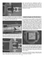
❏
8. Locate the 3/4" x 3/4" x 1" [19mm x 19mm x 25mm]
hardwood block. On the side that is 1" [25.4mm] long, drill a
3/32" [2.4mm] hole in the center of the block.
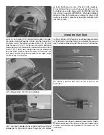
❏
9. Install the brass bushing into the nylon bellcrank.
Screw the bellcrank assembly to the wood block with a
#4 x 1/2" [12.7mm] screw. Be sure to orient the bellcrank
arm as shown. Enlarge the outer hole in both ends of the
bellcrank with a 5/64" [2mm] drill bit.
❏
10. Locate a 2-56 x 6" [152mm] wire pushrod. Cut the
threads so only 3/8" [9.5mm] of thread remain. Cut the
unthreaded end of the wire so that the overall length of
the wire pushrod including the remaining thread is 4-7/16"
[112mm]. Bend the un-threaded end of the wire 1/4" [6.4mm]
from the end of the wire. Screw a nylon ball link onto the
threaded end of the wire. Screw the nylon ball on so that it
completely covers the threads.
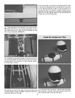
❏
11. Install the pushrod wire as shown. Slide the bent end
of the wire into the lower hole in the fi rewall. Attach the nylon
ball link onto the ball on the choke arm. Position the bellcrank
assembly inside the fuselage. Attach the pushrod from the
choke to the outer hole in the bellcrank and secure it with
a nylon FasLink
™
. Move the choke am back towards the
fi rewall. Now position the block so the other arm is positioned
as shown in the photograph. Glue the block in place with CA
glue. Once the glue has hardened drill two 1/16" [1.6mm]
holes in the fi rewall box and into the block. Install a #2 x 3/8"
[9.5mm] wood screw into each of the holes you drilled.

