


INTRODUCTION ................................................................2
AMA ...................................................................................2
SAFETY PRECAUTIONS ..................................................2
ADDITIONAL ITEMS REQUIRED .....................................3
Hardware and Accessories..........................................3
Engine..........................................................................3
Adhesives and Building Supplies.................................3
Optional Supplies and Tools ........................................3
IMPORTANT BUILDING NOTES.......................................4
COMMON ABBREVIATIONS ............................................4
KIT CONTENTS.................................................................5
ORDERING REPLACEMENT PARTS...............................6
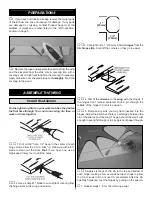
PREPARATIONS................................................................7
ASSEMBLE THE WING .....................................................7
Install the Ailerons .......................................................7
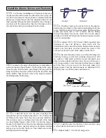
Install the Aileron Servos and Pushrods .....................8
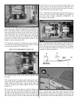
Join the Wing ...............................................................9
ASSEMBLE THE FUSELAGE .........................................10
Install the Stab, Elevators and Rudder ......................10
Install the Landing Gear and Wheel Pants ................12
Install the Engine, Fuel Tank and Throttle Servo .......12
Install the Cowl ..........................................................14
Install the Radio System ............................................15
FINAL TOUCHES.............................................................17
Install the Pilot and Canopy .......................................17
Apply the Decals........................................................17
GET THE MODEL READY TO FLY..................................17
Check the Control Directions .....................................17
Set the Control Throws ..............................................17
Balance the Model (C.G.) ..........................................18
Balance the Model Laterally ......................................19
PREFLIGHT .....................................................................19
Identify Your Model.....................................................19
Charge the Batteries..................................................19
Balance Propellers.....................................................19
Ground Check............................................................19
Range Check .............................................................19
ENGINE SAFETY PRECAUTIONS .................................20
AMA SAFETY CODE ......................................................20
CHECK LIST....................................................................20
FLYING.............................................................................21
Takeoff .......................................................................21
Flight ..........................................................................22
Landing ......................................................................22
ENGINE MOUNT TEMPLATE..........................................23
Congratulations on your purchase of the Great Planes CAP
580. We have painstakingly reproduced the airplane which
has been flown in shows throughout the U.S.A. by aerobatic
champion Matt Chapman. We think you will enjoy the way it
flies as well as the compliments you get every time you bring
it to the flying field.
For the latest technical updates or manual corrections to the
CAP 580 .40 -.70 ARF visit the Great Planes web site at
www.greatplanes.com. Open the “Airplanes” link, then select
the CAP 580 ARF. If there is new technical information or
changes to this model a “tech notice” box will appear in the
upper left corner of the page.
We urge you to join the AMA (Academy of Model Aeronautics)
and a local R/C club. The AMA is the governing body of model
aviation and membership is required to fly at AMA clubs.
Though joining the AMA provides many benefits, one of the
primary reasons to join is liability protection. Coverage is not
limited to flying at contests or on the club field. It even applies
to flying at public demonstrations and air shows. Failure to
comply with the Safety Code (excerpts printed in the back of
the manual) may endanger insurance coverage. Additionally,
training programs and instructors are available at AMA club
sites to help you get started the right way. There are over
2,500 AMA chartered clubs across the country. Contact the
AMA at the address or toll-free phone number below:
Academy of Model Aeronautics
5151 East Memorial Drive
Muncie, IN 47302-9252
Tele. (800) 435-9262
Fax (765) 741-0057
Or via the Internet at:
http://www.modelaircraft.org
IMPORTANT!!! Two of the most important things you can do
to preserve the radio controlled aircraft hobby are to avoid
flying near full-scale aircraft and avoid flying near or over
groups of people.
1. Your CAP 580 should not be considered a toy, but rather
a sophisticated, working model that functions very much like
a full-size airplane. Because of its performance capabilities,
the CAP 580, if not assembled and operated correctly, could
possibly cause injury to yourself or spectators and damage
to property.
2. You must assemble the model according to the
instructions. Do not alter or modify the model, as doing so
may result in an unsafe or unflyable model. In a few cases
the instructions may differ slightly from the photos. In those
instances the written instructions should be considered
as correct.
PROTECT YOUR MODEL, YOURSELF
& OTHERS...FOLLOW THESE
IMPORTANT SAFETY PRECAUTIONS
AMA
INTRODUCTION
TABLE OF CONTENTS
2


