


❏
6. Be sure the rudder servo is centered. Enlarge the first
hole in the servo arm with a Hobbico Servo Horn Drill (or a
#48 or 5/64" [2mm] drill bit). Center the rudder and align the
wire pushrod with the hole in the end of the servo arm. Use
a fine-point felt-tip pen to mark the wire where it crosses the
holes in the servo arm. On that mark make a 90 degree
bend. From the bend measure an additional 3/16" [4.8mm]
and then cut off the excess pushrod wire. Install a nylon
Faslink to the wire and servo arm.
❏
7. Install the elevator servo into the servo tray. Position it
in line with the elevator pushrods. Mount the servo using the
same procedure used for the rudder servo.
Refer to this photograph for steps 8-10.
❏
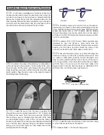
8. Make a bend in one of the elevator pushrod wires
as shown.
❏
9. Screw a 6-32 x 1/4” [6mm] socket head cap screw with
a small amount of threadlocker into two 5-32” [4mm] wheel
collars. Slide the wheel collars onto the wires. Align the
elevators. Tighten the set screws against the wires. Cut the
excess wire.
❏
10. Be sure the elevator servo is centered. Enlarge the
first hole in the servo arm with a Hobbico Servo Horn Drill
(or a #48 or 5/64" [2mm] drill bit). Center the elevators and
align the wire pushrod with the hole in the end of the servo
arm. Using a marker, mark the location where the wire aligns
with the hole in the servo arm. On that mark make a 90
degree bend. From the bend measure an additional 3/16"
[4.8mm] and then cut off the excess pushrod wire. Install a
nylon Faslink to the wire and servo arm.
❏
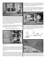
11. Install the switch and charge jack that came with your
radio on the side of the fuselage opposite the muffler. We
used the Ernst Charge receptacle (ERNM3001) for
mounting the charge jack.
❏
12. Install the battery and receiver as shown. Wrap 1/4”
thick foam around the receiver and battery, holding it in
place with the Velcro material included with the kit. Note:
You can switch the position of the receiver and battery as
needed for balancing purposes.
❏
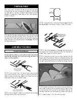
13. Use an arm cut from a servo arm to make an antenna
strain relief as shown. Insert the receiver antenna into the
white antenna tube. Hold it to the fuselage by placing a small
rubber band around the tail wheel and the end of the antenna.
16


