GREAT PLANES Li'l Poke Instruction Manual Download Page 22

No matter if you fly at an AMA sanctioned R/C club site or if you
fly somewhere on your own, you should always have your
name, address, telephone number and AMA number on or
inside your model. It is 

required

at all AMA R/C club flying sites

and AMA sanctioned flying events. Fill out the identification tag
on the back cover and place it on or inside your model.

Before flying you should perform one last overall inspection
to make sure the model is truly ready to fly and that you
haven’t overlooked anything. If you are not thoroughly
familiar with the operation of R/C models, ask an
experienced modeler to perform this inspection. Check to
see that the radio is installed correctly and that all the
controls are connected properly. The motor must also be
checked by confirming that the prop is rotating in the correct
direction and the motor sounds like it is reaching full power.
Make certain all control surfaces (elevators, rudder,
ailerons-if used) are secure, the pushrods are connected,
the controls respond in the correct direction, radio
components are securely mounted, and the C.G. is correct.

Ground check the operational range of the radio before the
first flight of the day. With the transmitter antenna collapsed
and the receiver and transmitter on, you should be able to
walk at least 100 feet away from the model and still have
control. Have an assistant stand by the model and  while
you work the controls, tell you what the control surfaces are
doing. Repeat this test 

with the motor running

at various

speeds. If the control surfaces do not respond correctly, 

do

not fly!

Find and correct the problem first. Look for loose

servo connections or broken wires, corroded wires on old
servo connectors, poor solder joints in your battery pack or
a defective cell, or a damaged receiver crystal from a
previous crash.

For the longest flight duration, and to get the most from a new
battery, the battery should be cycled. “Cycling” a battery means
to fully charge (“peak” charge) the battery, then to discharge it.
Many  battery chargers have peak charging and automatic
discharging capabilities. If you do not have a charger that is
able to discharge batteries, you can discharge the battery
yourself by running the motor with the propeller attached until
the propeller barely continues to turn. Charge and discharge
the battery 3 or 4 more times on the ground before flying. Be
sure to remove the battery from the airplane between each
cycle and allow it to cool before recharging.

Use fine sandpaper to remove imperfections along the
edges of the propeller. For the best performance, use a Top
Flite Precision Magnetic Prop Balancer™ (TOPQ5700) to
balance the propellers (this is a necessity on glow-powered
engines, but is less critical on small electric models).

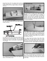
Make two more long rubber bands by connecting two sets
of two #32 rubber bands. Mount the wing with all four rubber
bands criss-crossing the last two.

1. Using multiple battery packs for successive flights may
cause the motor to become excessively hot, thus causing
damage. Allow the motor to cool for at least 10 minutes
between flights.

2. The ideal power source for the Li’l Poke system is a 7 or
8-cell (8.4 - 9.6volt) battery pack. The use of a higher voltage
battery may reduce motor life.

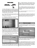
If taking off from the ground, the wheels must spin freely.
Put a drop of oil on each axle and check the wheels for
binding when moved from side to side.

Note:

Failure to follow these safety precautions may result

in severe injury to yourself and others.

Get help from an experienced pilot when learning to operate
the motor.

Use safety glasses when running the motor.

Do not run the motor in an area of loose gravel or sand; the
propeller may throw such material in your face or eyes.

Keep your face and body as well as all spectators away from
the path of the propeller as you start and run the motor.

Keep items such as these away from the prop: loose
clothing, shirt sleeves, ties, scarfs, long hair or loose objects
(pencils, screw drivers) that may fall out of shirt or jacket
pockets into the prop.

MOTOR SAFETY PRECAUTIONS

Oil the Wheels

Motor Care

Mount the Wing

Examine the Propeller

Cycle the Batteries

PERFORMANCE TIPS

Range Check

Ground Inspection

Identify Your  Model

22

Summary of Contents for Li'l Poke

Page 1: ...all be assumed nor accepted for any damage resulting from the use by the user of the final user assembled product By the act of using the user assembled product the user accepts all resulting liabilit...

Page 2: ...ty The Li l Poke is a slow flying model that is simple to build It is ideal for modelers with moderate flight experience or even experienced modelers who simply wish to try out a small lightweight ele...

Page 3: ...he AMA at the address or toll free phone number below Academy of Model Aeronautics 5151 East Memorial Drive Muncie IN 47302 9252 Tele 800 435 9262 Fax 765 741 0057 or via the Internet at http www mode...

Page 4: ...ctric flight GPMG0430 This system includes a T 280 Ferrite Motor S 280 4 1 1 ratio gearbox 3mm prop adapter APC 10 x 4 7 propeller and the ElectriFly C 10 Nano High Frequency Electronic Speed Control...

Page 5: ...ifficult to sand Use the included CA applicator tips to control and pinpoint the amount of CA that comes from the bottle When the tip becomes clogged cut the tip off and continue If additional CA tips...

Page 6: ...6 LASER CUT PATTERNS...

Page 7: ...t sandpaper by hand carefully round the trailing edge 5 Build the fin stab and elevators the same as the rudder When building the elevators bevel the leading edges and round the trailing edges but do...

Page 8: ...eeting from a 1 32 x 3 x 15 8 x 76 x 380mm balsa sheet The forward sheet should be cut approximately 1 8 3 2mm oversize so it can extend to the leading edge dowel Glue the sheeting to the spars and tr...

Page 9: ...bbing between the W1 ribs extends to 1 32 8mm below the top surface of the top spar to accommodate the top sheeting 15 Sheet the top of the center section between the two spars 16 Remove the center se...

Page 10: ...set rib W4 at the correct angle and glue it into position 8 Glue the top trailing edge sheet into position Cut the leading edge dowel to the correct length from the 1 8 x 24 3 2 x 610mm hardwood dowel...

Page 11: ...es of epoxy 4 Glue in the rest of the 1 32 8mm shear webbing between the ends of the polyhedral braces and ribs W2 Skip this section if not building ailerons Only the left aileron is shown in the phot...

Page 12: ...e right torque rod is a little longer than the left 10 Make two torque rod supports from leftover 1 16 1 6mm balsa When resting on the supports the torque rods should align with the bottom surface of...

Page 13: ...r cut 1 16 1 6mm balsa fuselage sides to the side view of the plan making certain they are accurately aligned with each other and the plan Align a small straightedge with the front of former F1 where...

Page 14: ...s to the formers and top deck 11 Cut the forward wing landing gear dowel and the aft wing dowel to a length of 3 1 2 90mm from the remainder of the 1 8 dowel used for the leading edge of the outer pan...

Page 15: ...he laser cut 1 16 1 6mm balsa former tops F1T through F6T to the top of the fuselage where shown on the plan 1 If you ve built the wing with ailerons remove the bottom horizontal brace from former F4...

Page 16: ...on the stringer in the top of the formers Holding the fin in position use a small builder s square to make certain it is perpendicular to the stab When the fin is in alignment glue it into position w...

Page 17: ...top gearbox mounting screw with your screwdriver Glue the nose sheeting into position The same as the cockpit sheeting feather the nose sheeting to the stringers with strips of 1 32 x 1 8 8 x 3 2mm ba...

Page 18: ...l and permanently glue in the aft wing dowel and the forward landing gear dowel 3 Make the tail skid as shown on the plan from leftover 1 8 x 1 4 3 2 x 6 4mm balsa Remove the covering from the bottom...

Page 19: ...5 Hinge the ailerons to the wing with strips of cellophane tape while simultaneously using epoxy to glue the aileron torque rods inside the top surface of the ailerons Flip the wing upside down while...

Page 20: ...of the wing Place the battery on the bottom of the model where required to get it to balance This is where the battery pack must be installed in the fuse 4 Noting where the battery must be mounted ins...

Page 21: ...measure the throws at the widest part of the surface If necessary reposition the pushrods on the servo arms farther out for more throw closer in for less throw or use the ATV function on the transmit...

Page 22: ...Many battery chargers have peak charging and automatic discharging capabilities If you do not have a charger that is able to discharge batteries you can discharge the battery yourself by running the m...

Page 23: ...wn in small areas the best place to fly any R C model is at an AMA chartered club field Club fields are set up for R C flying making your outing safer and more enjoyable We recommend that you join the...

Page 24: ...at an altitude of approximately 20 feet 6 meters When the airplane is approximately 50 to 100 feet 15 to 30 meters past you reduce motor power and make the final 180 degree turn into the wind alignin...

Page 25: ......

Page 26: ......

Reviews: