


❏
13. Drill #68 (or 1/32" [.8mm]) holes through the marks in
the laser-cut 1/16" [1.6mm] plywood
servo wheel
. Roughen
the top of the plastic servo arm that came with the servo so
glue will adhere. Glue the plywood servo wheel to the top of
the servo arm.
❏
14. Make the
aileron pushrods
from the remaining piece
of .030" [.76mm] wire you used to make the torque rods.
Use needle-nose pliers to make Z-bends on the ends of the
pushrods and connect them to the servo wheel and the
torque rods.
Set the wing aside and get started on the fuse.
❏
1. Cover the front view of the fuselage formers on the
plan with Great Planes Plan Protector.
❏
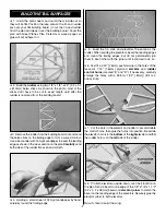
2. Just the same as the tail surfaces were built, build
formers
F1
through
F6
over the plan using three 1/8" x 1/8"
x 24" [3.2 x 3.2 x 610mm] balsa sticks. After the glue
hardens remove the formers from the plan and lightly sand
them flat and even.
Note:
Most of the formers are different
enough to easily identify, except for formers F2 and F5, so
label both formers so they don’t get switched later.
❏
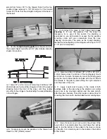
3. Pin both laser-cut 1/16" [1.6mm] balsa
fuselage sides
to the side-view of the plan making certain they are
accurately aligned with each other and the plan. Align a
small straightedge with the front of former F1 where
indicated by the tick-marks on the plan. Stick a T-pin through
both fuse sides near the top and bottom along the
straightedge.
❏
4. Mark the location of the rest of the formers the same
way. When the fuse sides are separated, the pinholes will
mark the location of the formers.
❏
5. Remove the fuse sides from the plan. Place them together
on your workbench so the top edges are contacting each other.
Label the bottom side as “R” and the other as “L”. Mark the
locations of the front edge of the formers by drawing a line
across the pinholes with a straightedge and a ballpoint pen.
❏
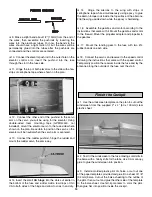
6. Cut the
firewall alignment template
from the plan.
Align the aft edge of the template with the line noting former
F1. Use a ballpoint pen to mark the front edge of the firewall
using the template as a guide.
❏
7. Accurately cut the
top deck template
from the plan.
Use the template to make the
top deck
from the excess
1/32" [.8mm] sheeting on the end of the die sheet that the
forward and aft fuse bottom come from.
Frame the Sides
BUILD THE FUSELAGE
13