GREAT PLANES EXTRA-300SP Instruction Manual Download Page 16

16

hatch, using thin or thick CA. Once the CA dries, place the 
remaining two magnets over the ones mounted in the hatch. 
Make a mark on the unmounted magnets. This mark will be 
used to determine which way the magnets should face when 
they are inserted into the fuselage.

 3. Using thin or thick CA, glue the unmounted magnets 

into the fuselage with the marks facing into the mounting 
holes. Once the CA has had time to fully cure, install the 
hatch by sliding the hatch dowels into the openings in the 
front former, laying the hatch on the fuselage, and sliding the 
hatch toward the tail to lock it into place.

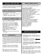
 4. Locate the two plywood washers. Install the plywood 

washers around the hatch alignment dowels. Press down 
on the front of the hatch slightly and, using some thick CA, 
tack the plywood washers in place as shown. Spray some 
activator on the CA to stop it from wicking onto the hatch 
dowels. Gently remove the hatch, while placing counter 
pressure to the washers so they do not come unglued. With 
the hatch removed, apply more thick CA or 6 minute epoxy 
around the washer to fully secure it to the fuselage.

 5. Locate the canopy and the four #2 x 3/8" sheet metal 

screws. Install the canopy, making sure that the leading edge 
of the canopy sits fl ush with the top of the hatch. Drill a 1/16 
[1.5mm] hole through the canopy and through the front two 
plywood mounting plates. Insert a wood screw into each 
hole, remove the screws, and add two drops of thin CA to 
the holes. Install the front two canopy screws.

 6. Lightly pull the canopy rearward against the two mounting 

screws you installed. Drill a 1/16" [1.5mm] hole through the 
canopy and rear mounting plates. Install the rear canopy 
screws, remove them, and harden the hole with CA. Trim the 
canopy screws with a rotary tool or diagonal pliers until they 
sit fl ush with the inside of the canopy mounting plate. 

 7. If you would like to install a pilot fi gure and a scale 

instrument panel, this would be the appropriate time to 
mount them. Clean the inside of the canopy and install it. 
View the canopy from the front, making sure the front of the 
canopy sits fl ush with the hatch.

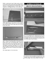
Install the Electric Motor 

and Rudder Servo

 1. If you are using a glow engine instead of an electric 

motor, skip ahead to page 19.


 2. To use the Great Planes Large Electric Motor Mount 

(GPMG1260) with this model, you’ll need to make a few 
modifi cations. With a permanent marker, mark both sides of 
the two motor mount pieces as shown.

 3. Cut the motor mount with a hack saw or rotary tool along 

the line (this will remove approximately 3/4" [19mm] from the 
mount). Mount the electric motor using the 3mm machine 
screws supplied with it. Be sure to use thread locker.

Summary of Contents for EXTRA-300SP

Page 1: ...e place of purchase To make a warranty claim send the defective part or item to Hobby Services at the address below Hobby Services 3002 N Apollo Dr Suite 1 Champaign IL 61822 USA Include a letter stat...

Page 2: ...attributes of both power systems Two rudder placement locations and alternate battery mounting positions have been included to eliminate the need for lead ballast This modeliscapableofthemostextreme3D...

Page 3: ...ants included in this kit are made of fiberglass the fibers of which may cause eye skin and respiratory tract irritation Never blow into a part wheel pant cowl to remove fiberglass dust as the dust wi...

Page 4: ...e risk of damaging the batteries during charging A suitable balancer for the Great Planes ElectriFly Power Series LiPo batteries is the Great Planes ElectriFly Equinox LiPo Cell Balancer GPMM3160 If n...

Page 5: ...750 or Top Flite MonoKote sealing iron TOPR2100 Top Flite Hot Sock iron cover TOPR2175 Top Flite MonoKote trim seal iron TOPR2200 Optional Supplies and Tools Here is a list of optional tools mentioned...

Page 6: ...ight deviations between your model and the published values ORDERING REPLACEMENT PARTS Replacement parts for the Extra 300SP 46 ARF are available using the order numbers in the Replacement Parts List...

Page 7: ...art names exactly as they are written in the Kit Contents list Great Planes Product Support 3002 N Apollo Drive Suite 1 Champaign IL 61822 Telephone 217 398 8970 ext 5 Fax 217 398 7721 E mail airsuppo...

Page 8: ...ron This will allow the CA glue to properly wick through the entire hinge 2 Temporarily insert a T pin into the middle of each hinge This will be used to properly align the hinge when mating the ailer...

Page 9: ...veral occasions where epoxy cleanup will be necessary Instead of wasting whole paper towels stack three or four paper towels on top of each other and cut them into small squares This will conserve pap...

Page 10: ...7 Using the radio and receiver center the servo and attach the control horn as shown If any other arms are present on the servo remove them with a rotary tool or a pair of diagonal pliers Enlarge the...

Page 11: ...he control horn but do not snap in place Connect the bent end to the servo Re center the servo and adjust the linkage by screwing the clevis either in or out until the aileron is straight Once the ail...

Page 12: ...cut portion of the covering remove that section of the covering Be careful not to cut into the wood when removing the covering Use a soldering iron to cut the covering The tip of the soldering iron do...

Page 13: ...er as shown 3 Test fit the tail wheel into both the fuselage and the rudder as shown If the tail wheel does not fit properly use a hobby knife to modify the mounts so the tail wheel fits snugly 4 Plac...

Page 14: ...the 4 40 x 1 4 SHCS as shown Be sure to place a drop of thread locker on the screw before inserting it 4 Trim the covering away from the three landing gear mounting holes and mount the landing gear t...

Page 15: ...e pushrod in place using a nylon FasLink 6 Trim the non bent elevator pushrod so that it is approximately 1 25 4mm shorter than the bent pushrod Place some thread locker on to the 6 32 x 1 4 6mm socke...

Page 16: ...sits flush with the top of the hatch Drill a 1 16 1 5mm hole through the canopy and through the front two plywood mounting plates Insert a wood screw into each hole remove the screws and add two drop...

Page 17: ...otation of the motor is not counter clockwise as viewed from the front of the airplane remove any two of the wires that connect the ESC to the motor and swap them Verify that the motor rotation is cor...

Page 18: ...nto the pushrod guide Hook the clevis onto the nylon swivel but do not snap it shut 13 Place the rudder servo into the mounting tray Mark the mounting holes and using a 1 16 1 6mm drill bit drill pilo...

Page 19: ...w for clearance of the fuel lines 3 Locate the throttle servo and install it as shown using the hardware provided with the servo Bend the pushrod and adjust it so that the throttle servo can move the...

Page 20: ...3 4 95mm long carbon tube over the pushrod leaving approximately 1 8 3mm from the threads to the carbon tube Install the pushrod onto the nylon swivel 9 Center the servo and the rudder Mark the locat...

Page 21: ...kip to step 4 in this section Install the hatch Locate some stiff paper or cardboard Tape the cardboard to the model and make cutouts in the cardboard for places where the cowl needs to be cut away Re...

Page 22: ...o Check the Control Directions in the next section Install and Connect the Motor Battery 1 Remove the propeller IMPORTANT Whenever setting up or working on an electric powered model always remove the...

Page 23: ...tteries with lower voltage will try to equalize with the batteries that have a higher voltage Current will flow from the higher voltage battery into the lower one essentially charging the lower voltag...

Page 24: ...ne whether or not your first flight will be successful If you value this model and wish to enjoy it for many flights DO NOT OVERLOOK THIS IMPORTANT PROCEDURE A model that is not properly balanced will...

Page 25: ...sanctioned R C club site or if you fly somewhere on your own you should always have your name address telephone number and AMA number on or inside your model It is required at all AMA R C club flying...

Page 26: ...ine an on off switch should be connected to the engine coil Do not throw anything into the propeller of a running engine These precautions apply only to electric powered models Always remove the LiPo...

Page 27: ...ycle your receiver battery pack if necessary and make sure it is fully charged 20 If you wish to photograph your model do so before your first flight 21 Range check your radio when you get to the flyi...

Page 28: ...cessive hinge gap Not mounting control horns solidly Poor fit of clevis pin in horn Side play of wire pushrods caused by large bends Excessive free play in servo gears Insecure servo mounting and one...

Reviews: