25
INSTALL THE OPTIONAL
MECHANICAL NOSE GEAR RETRACT
If you have already installed the fi xed nose gear, skip this
section.
❏
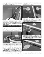
1. Use a rotary tool with a fi ne straight cutting bit (a hobby
knife could be used but is not the recommended tool) to make
elongated holes in the positions shown in the photo. Notice
that the holes are centered in the curve of the wheel well. As
you install your pushrods in later steps, these holes may need
to lengthened or widened to accommodate the pushrods.
❏
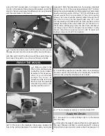
2. Cut the nose gear strut using the dimensions shown. A
rotary tool with a cut off wheel is recommended for shortening
the strut.
❏
3. Position the retract onto the rails in the retract well as far
forward as it will go. Temporarily slide the axle shown in step
11 onto the end of the gear strut to ensure the nose wheel will
be centered in the wheel well. Center the retract between the
rails and use a felt-tip pen to mark the mounting hole locations.
❏
4. Drill 3/32" [2.4mm] holes at the marks you made. Thread
a #4 x 1/2" [13mm] self-tapping screw into each hole and
back it out. Apply a drop of thin CA to the holes and allow the
glue to harden. Install the retract using four #4 x 1/2" [13mm]
self-tapping screws.
❏
5. If you are using the recommended retract servo, the servo
tray will need to be enlarged as shown. Measure your servo,
draw the desired cut lines onto the tray and make your cuts
using a rotary tool or a hobby knife. Wrap a piece of sandpaper
around a fl at, scrap piece of wood and fi nish sand the edges
for a professional looking modifi cation.
❏
6. Install the retract servo using the hardware included
with the servo. Be sure to harden the servo mounting holes
with thin CA.


