13
❏
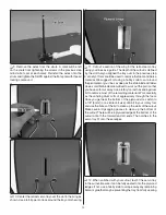
13. Use the hardware included with the retract servo to
mount it to the servo tray. Be sure to harden the servo mounting
holes with thin CA glue. Coat the notches of the tray with
epoxy as well as the plywood ledges in the cutout. Glue the
tray into the cutout.
❏
14. Check the rotation of your retract servo using your
radio. The servo shown in the picture will rotate clockwise to
raise the wheels into the wells. Attach two brass screw lock
connectors to a servo wheel (a two-armed servo arm would
also work) so that they are 1" [25mm] apart and positioned
slightly angled from being perpendicular to the servo case. To
ensure that the retracts open from lock to lock we recommend
setting the screw-lock connectors close to 1" [25mm] apart.
Loosely install two 4-40 set screws in the screw lock connectors.
❏
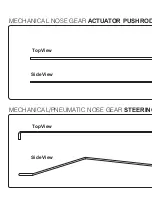
15. Thread a nylon clevis 20 complete turns onto a 12"
[305mm] pushrod. Insert the pushrod through the hole at the
inboard side of a wheel well. Align the pin in the clevis over
the actuator link on the retract when the retract is in the down
(landing) position. Make a mark on the wire just beyond the
hole in the wheel well.
❏
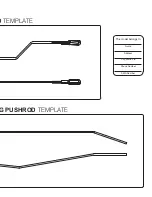
16. Make a shallow bend in the wire at your mark and
another bend just behind the threaded portion of the pushrod
(you may need to adjust the angles of the bends after you test
fi t the pushrod into the wing.
❏
17. Reinsert the pushrod into the wing and connect the
clevis to the actuator link on the retract. Rotate the link so it
is closest to the leading edge of the wing as shown. Make
any adjustments to the bends in the pushrod so that the wire
lays as close to the bottom of the wheel well as possible. The
pushrod must not interfere with the wheel going up into the
wheel well.
❏
18. Mark the pushrod where it meets the opposite edge
of the retract servo cutout in the wing (with the gear in the
landing position.) Cut off the excess pushrod at this mark.


