GREAT PLANES BLT Instruction Manual Download Page 5

Single-edge razor blades (HCAR0212)

Small T-pins (HCAR5100)

Builder’s triangle (HCAR0480)

Small Phillips and flat blade screwdrivers

Pliers with wire cutter (HCAR0630)

Great Planes Plan protector (GPMR6167) or wax paper

Sanding tools and sandpaper assortment

Sealing Iron (TOPR2100)

Double-sided foam tape (GPMQ4440) 

Here is a list of optional tools mentioned in the manual that
will help you build the BLT. 

Great Planes CG Machine

(GPMR2400)

Top Flite Precision Magnetic Prop Balancer

(TOPQ5700)

Top Flite Hot Sock

iron cover (TOPR2175)

Straightedge with scale (HCAR0475)

Cutting mat (HCAR0456)

Masking Tape (TOPR8018)

CA Debonder (GPMR6039)

CA Applicator tips (GPMR6033)

Great Planes 5-1/2” [140mm] Bar Sander (GPMR6169)

and 150-grit adhesive back sandpaper (GPMR6183)

Top Flite 320-grit sandpaper (TOPR8030) and 400-grit

sandpaper (TOPR8032) 

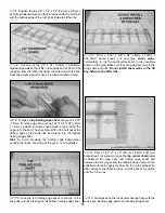
For the best performance, the BLT must be built light. One
of the best ways to insure light weight is to build neatly and
make good-fitting glue joints that require less glue. Here are
some tips to help you build neatly and light.

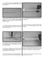
1. The easiest way to cut balsa sticks is with a single-edge
razor blade. To do so, position the stick over the plan, then
place the razor blade on the stick where you wish to cut it.
Press down lightly on the razor blade to make a mark where
the stick is to be cut. 

2. Take the stick off the plan and cut it over a cutting mat or
a scrap piece of wood (

Okay, if you’re careful you could go

ahead and cut the stick right over the plan, but if you do, you
may cut through the plan protector allowing the CA to soak
through and glue the structure to the plan

).

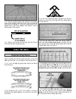
3. Because of the small balsa sticks used in the tail, only where

necessary

, we recommend using small T-pins (HCAR5100) or

small straight pins found in craft stores. Do not stick pins into
the sticks near the ends, or the wood may split.

4. If you have difficulty with the T-pins splitting the small
sticks, an alternate method is to use the “crossed-pin”
technique. Insert the T-pins into the building board in a
criss-cross fashion to hold the sticks to the plan.

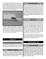
5. Only a small amount of CA should be used to glue the parts
together. Use the included CA applicator tips to control and
pinpoint the amount of CA that comes from the bottle. When
the tip becomes clogged, cut a short length of the tip off and
continue. In addition to unnecessary weight, excess CA is
difficult to sand. If you require additional CA tips, order no.
GPMR6033 (5).

6. When applying CA, be careful to not glue your fingers to the
structure. In the process of 

unsticking

your fingers you can

inadvertently damage the structure, thus requiring repairs and
adding additional weight 

(not to mention the aggravation!)

.

7. Sanding requires a light touch to avoid damage. We
found the best method for sanding is to use light strokes in
the direction of the longest sticks. Be certain the sandpaper
is 

thoroughly

bonded to the bar sander. Lifted edges will

catch the structure, causing damage. Use medium-grit
sandpaper such as 150 or 220.

8. One of the best ways to insure a lightweight model is to
proceed slowly and 

build neatly

. Good glue joints with minimal

adhesive are stronger, lighter and have a better appearance
than poor-fitting joints with too much CA. Of course, you should
take this approach with 

all

of your projects!

9. Work over a flat surface. Cover the plans with Great
Planes Plan Protector (GPMR6167) or wax paper so the
parts will not adhere to the plan.

IMPORTANT BUILDING NOTES

Optional Supplies and Tools

5

Summary of Contents for BLT

Page 1: ...resulting from the use by the user of the final user assembled product By the act of using the user assembled product the user accepts all resulting liability If the buyers are not prepared to accept...

Page 2: ...tu flying site see Find a Safe Place to Fly on page 21 Additionally Park Flyers are perfect for those evenings at the field when everybody else is packing up their gear the wind has died and there is...

Page 3: ...ired to power the radio The Great Planes ElectriFly C 5 Nano High Frequency Electronic Speed Control GPMM2000 is recommended for the BLT If you purchase the complete motor and gear drive system the sp...

Page 4: ...asonic 7 cell 1200 mAh NiMh GPMP0300 for advanced pilots requiring the longest duration not recommended for beginners due to the fact that it is heavier than the 550 mAh batteries Note If flying the B...

Page 5: ...ed in the tail only where necessary we recommend using small T pins HCAR5100 or small straight pins found in craft stores Do not stick pins into the sticks near the ends or the wood may split 4 If you...

Page 6: ...2 2 4mm 1 8 3 2mm 5 32 4mm 3 16 4 8mm 1 4 6 4mm 3 8 9 5mm 1 2 12 7mm 5 8 15 9mm 3 4 19mm 1 25 4mm 2 50 8mm 3 76 2mm 6 152 4mm 12 304 8mm 15 381mm 18 457 2mm 21 533 4mm 24 609 6mm 30 762mm 36 914 4mm M...

Page 7: ...with 220 grit sandpaper very lightly sand the fin all over Be sure to sand in the direction of the longest sticks 6 Tape the leading edge of the rudder to the trailing edge of the fin so that the fin...

Page 8: ...r gussets of one of the elevators 5 Repeat step 4 to build the second elevator half 6 In the right elevator half use a hobby knife to cut the 1 16 1 6mm notch for the elevator control horn 7 Tape the...

Page 9: ...ill counteract each other 3 Pin one of the main spars in position over the plan aligning one end of the main spar with the outside edge of the root rib W1A 4 Pin one of the 1 32 x 3 4 x 24 8mm x 19mm...

Page 10: ...ing edge sheet when sanding the taper sand across the grain not lengthwise 10 Glue the top trailing edge sheet to the top of the wing ribs and the aft edge of the bottom trailing edge sheet 11 From a...

Page 11: ...dihedral brace 2 Using a hobby knife carefully cut a 1 16 slot in rib W1A just behind the main spar on both wing panels Trial fit the dihedral brace in the slots 3 Trial fit the wing halves together W...

Page 12: ...inst the building board Glue the second fuselage side to the fuselage bottom and the five formers Note You may need to sand the formers flush with the side and bottom 6 Remove the pins holding the fus...

Page 13: ...ront of the wing pylon to act as a spacer Glue the laser cut 3 32 2 4mm balsa pylon forward plate to the forward end of the wing pylon The forward plate should be flush with the sides of the wing pylo...

Page 14: ...he wing to first stall next to the fuselage not at the tip Because the Basic Light Trainer is designed to be very light washout would be difficult to build into the wing The following procedure will e...

Page 15: ...t the fuselage is not twisted If it is dampen the fuse slightly and twist it in the opposite direction until the wood dries Recheck the stabilizer wing alignment When satisfied with the fit use thin C...

Page 16: ...r battery out through the front You can glue a couple of small pieces of the white tube to the bottom of the fuselage and route the receiver antenna through the tubes towards the tail Follow these ass...

Page 17: ...ops of CA along the joint between the motor and the motor wedge to secure the motor 4 Plug the motor into the electronic speed control Secure the motor and electronic speed control wires to the fusela...

Page 18: ...the pushrod adjuster 9 Remove the aft pushrod from the control horn and cut it at the mark Make a slight bend in the end of the pushrod so that it fits tightly in the pushrod adjuster 10 Remove the s...

Page 19: ...Trainer you may wish to experiment by shifting the balance up to 1 4 forward or backward to change its flying characteristics Moving the balance forward may improve the smoothness and stability but t...

Page 20: ...full power and the prop is rotating in the correct direction Make certain all control surfaces elevators and rudder are secure the pushrods are connected the controls respond in the correct direction...

Page 21: ...ENERAL 1 I will not fly my model aircraft in competition or in the presence of spectators until it has been proven to be airworthy by having been previously successfully flight tested 2 I will not fly...

Page 22: ...irm that the transmitter operates the controls by moving the sticks and watching the surfaces respond Occasionally electric models have been launched with the transmitter turned off or the battery dis...

Page 23: ...frequently a takeoff from the ground is called an ROG rise off ground takeoff Landings on grass will be a little rough but doing a ROG takeoff from grass will probably not be possible with the BLT If...

Page 24: ...TWO VIEW...

Reviews: