


Great Plains | 166-486M | 2020/10/08
46
Spartan
II
607
Operation
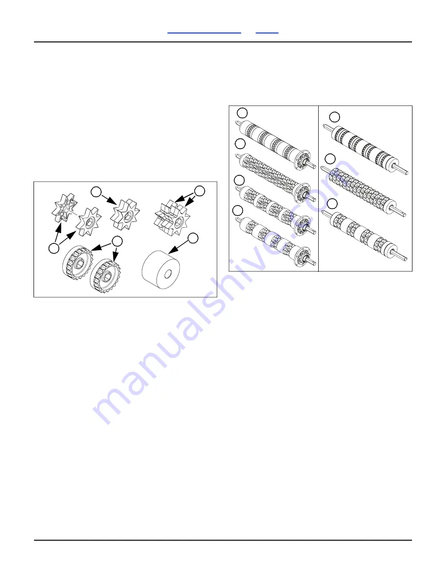
Metering Shafts
The configuration of the metering shaft (number and
type of stars) effects the seeding rate.
A star (1) for a 2-, 3-, and 4
-
star metering shaft is
made of two halves (2) that are aligned. Each star is
offset from the adjoining star (3).
Stars for small seed (4) are made of two halves that
are not aligned. For a lower small seed planting rate
than the chart on page 56, plastic spacers (5) can be
used. To use the spacers, disassemble the small
seeds shaft and replace half of a small seeds star
assembly with a spacer. The spacers are stored in
the tool box.
If the material rate needs to be changed, first find the
configuration of the metering shaft. It is not
necessary to remove the metering shaft to determine
the configuration.
To determine the configuration of the metering shaft
installed in the drill:
First make sure the hoppers and the meters are
empty. See “
Inspect the metering shaft from the hopper lid. Do
not enter the hopper.
Inspect the metering shaft more closely from
under the meter with the front meter door fully
open.
Compare the metering shaft to the ones below.
(1) small seed rate metering shaft.
(2) 4
-
star metering shaft. (Factory installed.)
(3) 3-star metering shaft (S/N C1009F- only).
(4) 2
-
star metering shaft.
Changing a Metering Shaft
The hopper must be empty for this procedure.
For S/N C1009F-
If your seeding rates need to be lower, select one of
the lower rate shafts.
Replace the standard 4
-
star metering shaft with a
3
-
star metering shaft to decrease the seeding
rate by approximately 25% (to 75% of standard
rate).
Replace the standard 4
-
star metering shaft with a
2
-
star metering shaft to decrease the seeding
rate by approximately 50% (to 50% of standard
rate).
For compatible seeds, replace the standard
4
-
star metering shaft with the small seeds
metering shaft to reduce the seeding rate by
approximately 90 to 75% (to a net of 10% to 25%
of standard rate).
For small seeds or other seeds smaller than 12 to
4.7 mm, the standard metering shaft may not
provide enough precision and uniform flow at
very low rates.
To order other metering shafts, see “
5
4
1
3
2
32400A
S/N C1009F-
S/N
4
2
3
1
1
2
4
Summary of Contents for SPARTAN II
Page 12: ...Great Plains 166 486M 2020 10 08 6 SpartanII 607 Table of Contents Index Safety Information ...
Page 125: ...Great Plains 166 486M 2020 10 08 118 SpartanII 607 Table of Contents Index ...
Page 127: ...Great Plains 166 486M 10 08 2020 120 SpartanII 607 Table of Contents Index Warranty ...
Page 130: ...Table of Contents Index ...
Page 131: ...Great Plains Mfg 1525 E North St P O Box 5060 Salina KS 67402 ...