background image

Read the operator manual entirely. When you see
this  symbol,  the  subsequent  instructions  and
warnings  are serious 

-

 follow  without exception.

Your life and the lives of others depend on it!
Illustrations  may  show  optional  equipment  not
supplied with standard unit.

!

Table of Contents

Index

Original Instructions

411-681M

Great Plains

OPERATOR MANUAL

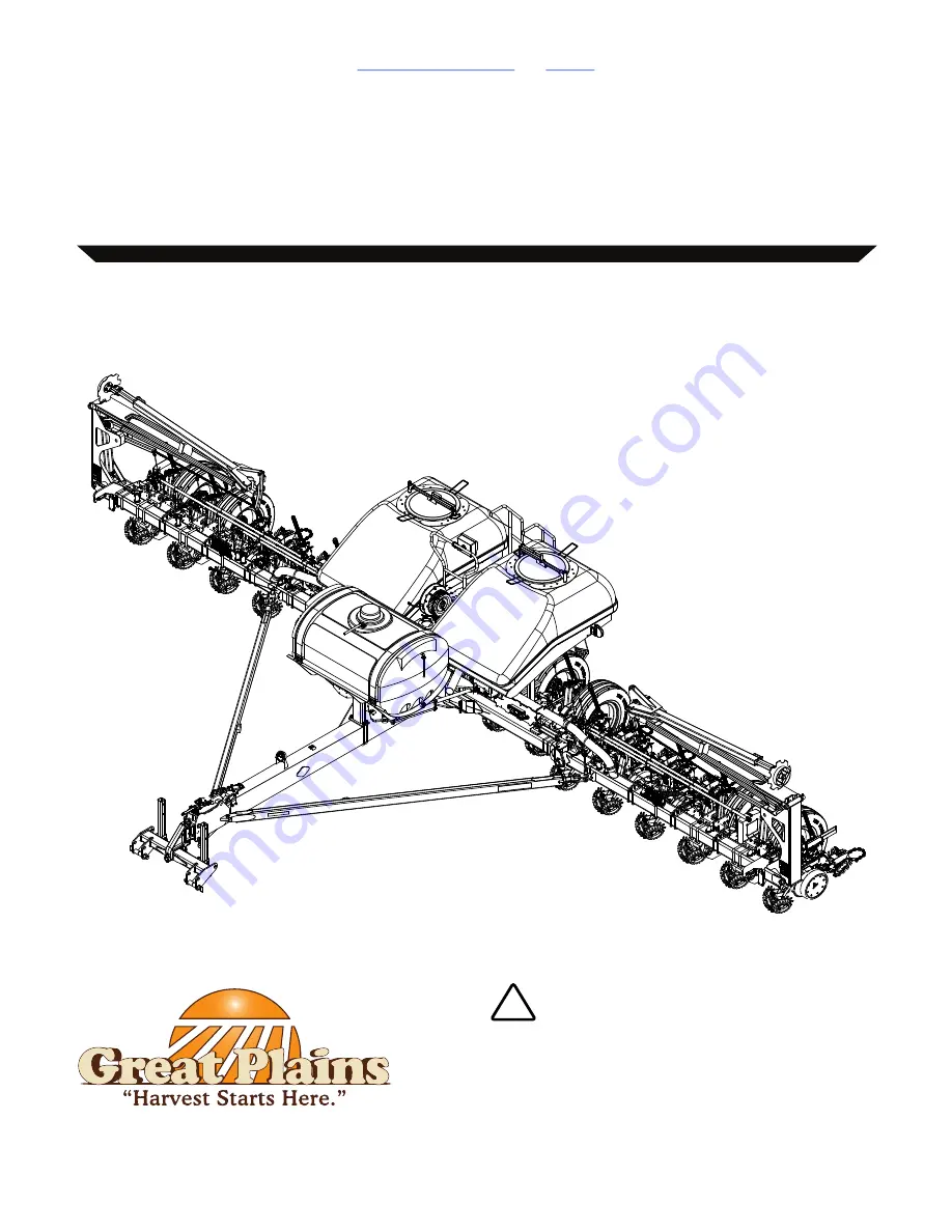
MODEL PL5700 3-Section Planter

PLANTER

Summary of Contents for PL5700

Page 1: ...d warnings are serious follow without exception Your life and the lives of others depend on it Illustrations may show optional equipment not supplied with standard unit Table of Contents Index Original Instructions 411 681M Great Plains OPERATOR MANUAL MODEL PL5700 3 Section Planter PLANTER ...

Page 2: ...ered the weights and measurements are no longer accurate for your machine Update the record by adding the machine weight and measurements with the option s weight and measurements Dealer Contact Information Model Number Serial Number Machine Height Machine Length Machine Width Machine Weight Year of Construction Delivery Date First Operation Accessories Name Street City State Telephone Email Deale...

Page 3: ...y before using the machine It will familiarize you with safety operation adjustments and maintenance of your new equipment This manual must always be kept with your machine Great Plains wants you to be satisfied with your product If for any reason you do not understand any part of this manual or are otherwise dissatisfied please take the following actions first 1 Discuss the matter with your deale...

Page 4: ...nclude Air Pro Clear Shot Discovator Great Plains Land Pride MeterCone Nutri Pro Seed Lok Solid Stand Terra Guard Turbo Chisel Turbo Chopper Turbo Max Turbo Trill Ultra Till Whirlfilter and Yield Pro Brand and product names that appear and are owned by others are trademarks of their respective owners For permission requests write to the publisher at the address below Great Plains Mfg 1525 E North ...

Page 5: ...n 17 Pre Start Checklist 17 Field Operation 17 Before Planting Checklist 17 Begin Planting 17 End Planting 17 Transport Locks 18 Wing Hooks 18 Cylinder Locks 18 Tongue Hook Latch 19 Operation Controls 19 IntelliAg ISO6 19 PL5700 Switch Box 19 Raising Lowering Tongue 19 Raising Lowering Wing Gauge Wheels 20 With IntelliAg ISO6 20 With Switch Box 20 Raising the Planter 21 With IntelliAg ISO6 21 With...

Page 6: ...53 Loading Materials 54 Orifice Plates 54 Orifice Plate Installation 55 Strainer 55 Relief Valve 55 Setting Fertilizer Rate 55 Fertilizer Ground Drive 55 Fertilizer Hydraulic Drive 56 AccuShot Fertilizer System Option 57 Fertilizer Section Control System Option 57 Parking 57 Transport 57 Maintenance 58 Maintenance Schedule 58 Regular Maintenance 58 Hydraulic System 59 Hydraulic System Inspection 5...

Page 7: ...er Planters 94 Row Hopper Planters 96 Field Working Dimensions 97 Hydraulic Diagrams 101 Lift Hydraulics 12 Row Planters 101 Lift Hydraulics 16 Row Planters 102 Fold Hydraulics 103 Dual Fan Hydraulics Bulk Hopper 104 Single Fan Hydraulics Row Hopper 105 Marker Hydraulics 106 Weight Transfer Hydraulics 107 Liquid Fertilizer Plumbing Diagrams 108 30 Row Spacing Plumbing S N E1008B 108 30 Row Spacing...

Page 8: ...n ordering parts from your dealer Record your planter model and serial number on the inside cover of this manual for quick reference Target Group for Operator Manual Simplified Illustrations Illustrations of the machine in the operator manual are shown without protective equipment or with the protective equipment open for better understanding Be sure to observe the safety information and follow th...

Page 9: ...e 7 Never wear loose or bulky clothing around machine Use additional safety equipment such as hard hats eye and ear protection safety boots etc as needed 8 Do not modify the machine Unauthorized modification can result in unsafe conditions that lead to machine damage or personal injury Operation 1 Always stop the tractor and put the tractor gear in Park Turn off engine and remove the key before le...

Page 10: ...ork in a clean dry area 3 Lower the implement Put tractor gear in Park and turn off engine To prevent unauthorized starting remove key before performing maintenance or service work 4 If work must be performed with wings raised put cylinder locks on wing cylinders 5 Verify all moving parts have stopped and all system pressure is relieved 6 Relieve hydraulic pressure before disconnecting hydraulic l...

Page 11: ...ng can cause a trailer to swerve and upset Reduce speed if trailer is not equipped with brakes Safety Chain 1 Use a chain with a strength rating equal to or greater than the gross weight of towed machinery 2 Replace chain if any links or end fittings are broken stretched or damaged 3 Do not use safety chain for towing Safety Lights and Devices 1 Always use safety lighting Slow moving tractors and ...

Page 12: ...ecals To install new decals Clean the area on which the decal is to be placed Peel backing from decal Press firmly on surface being careful not to cause air bubbles under decal Slow Moving Vehicle Reflector 818 055C Bulk seed hoppers One reflector at rear of hoppers Row hopper planters One reflector on rear of fan Red Reflectors 838 614C Bulk seed hoppers four reflectors Two reflectors under each ...

Page 13: ...ers two reflectors One reflector on rear of each wing to face out when planter is folded Row hopper planters four reflectors One reflector on each end hopper mount to face front when folded and one on each outside wheel mount of center section Orange Reflectors 838 603C Bulk seed hoppers two reflectors One reflector under each hopper Row hopper planters two reflectors One reflector on each light b...

Page 14: ... RO TA TING DR IVEL INE CO NTAC T CA N CA US E DE ATH KE EP AW AY DO NO T OP ER ATE WITH OU T DANGER 858 0 29C CA PA CI TY 13 5 U S GAL S US E AN Y HIG H QU AL ITY MIN ER AL BA SE D HY DR AU LIC FL UID WI TH A VIS CO SIT Y RA TIN G OF 10W 30 OIL MU ST BE CL EA N AN D FR EE FR OM DIR T OR CO NT AM INA NT PA RT ICL ES TO PR EV EN T DA MA GE TO PU MP AN D MO TO R RE PL AC E FIL TE R EL EM EN T AF TE ...

Page 15: ... section top decal Overhead Hazard 818 580C Two decals On each marker first section middle decal Pinch Point Hazard 818 579C Two decals On each marker first section bottom decal 818 525C WARNING SHARPOBJECTHAZARD To prevent serious injury or Death from Sharp Objects Keep hands feet hair clothing away from tines DO NOT stand or climb on machine when operating Keep others away 68613 TP 71915 TP 7191...

Page 16: ...ss emb ly sec urel y atta che d with torq ue arm and clam p bolt s pro per ly torq ued RO TA TING DR IVEL INE CO NTAC T CA N CA US E DE ATH KE EP AW AY DO NO T OP ER ATE WITH OU T DANGER 858 0 29C CA PA CI TY 13 5 U S GAL S US E AN Y HIG H QU AL ITY MIN ER AL BA SE D HY DR AU LIC FL UID WI TH A VIS CO SIT Y RA TIN G OF 10W 30 OIL MU ST BE CL EA N AN D FR EE FR OM DIR T OR CO NT AM INA NT PA RT ICL...

Page 17: ...EA N AN D FR EE FR OM DIR T OR CO NT AM INA NT PA RT ICL ES TO PR EV EN T DA MA GE TO PU MP AN D MO TO R RE PL AC E FIL TE R EL EM EN T AF TE R EV ER Y 150 OP ER ATI NG HO UR S OR 2 YE AR S SE RV ICE LE VE L TO OL BA R BE FO RE CH EK ING OIL LE VE L OIL FILL LIN E 858 0 04C Rea d Own er s Man ual BEF ORE ope ratin g mac hine Kee p trac tor at IDLI NG SPE ED and slow ly eng age PTO to prev ent dam ...

Page 18: ... place any part or your body between planter and moving tractor Keep others away Failure to avoid may result in severe injury or death by being crushed between tractor and planter Stop tractor engine and set park brake before attaching harnesses or hoses High Pressure Fluid Hazard Escaping fluid under pressure can have sufficient pressure to penetrate the skin Check all hydraulic lines and fitting...

Page 19: ...e point arms and sway blocks to minimize side to side sway and assure proper tracking in the field and when transporting See your tractor s operator manual for information 4 Back the tractor to align the drawbar and hitch 5 Connect the tractor to the planter two point hitch If using a quick hitch be sure the planter locks into the hitch securely 6 Raise the hitch high enough to take pressure off t...

Page 20: ...w to safely complete hydraulic system work You should only maintain or adjust your hydraulic system as described within this manual Compromising a closed hydraulic system can cause serious injury or death Planter Damage Risk Do not fold or unfold without first fully raising planter completely or damage will occur The hydraulic system is fully charged and bled at the factory prior to shipping The f...

Page 21: ...lanters configured with 16 rows the two sensors are located on the outside wing gauge wheels Markers Electrocution Hazard Machine is not grounded To prevent serious injury or death keep clear of overhead power lines when transporting folding unfolding or operating all planter components At higher voltages electrocution can occur without direct contact Flailing Hazard Marker hydraulics are active w...

Page 22: ...ube 3 in or out to get the proper adjustment Marker Chain Length Planter Damage Risk Keep the marker chain slack within one inch 2 4 cm of 18 inches 46 cm A chain length too short or too long can result in marker or planter damage Correct chain slack will need to be set before first use Correct slack needs to be maintained with periodic checks Set the initial chain length perform chain slack check...

Page 23: ... Sensors Option If your planter is configured with bulk hoppers there are factory installed hopper level sensors inside the bulk hoppers Hopper level data will be display on the IntelliAg ISO6 capable in cab console Rear Auxiliary Hydraulics Option If the planter is equipped with an auxiliary hydraulic drive system set the selector valve 1 near the sequence valve 2 at the marker base on the left w...

Page 24: ...ver the fold hydraulics are not in use It is important to set the tractor fold marker hydraulic circuit lever to Float or Neutral to prevent unintended marker operations Unexpected marker operation and flailing equipment can serious injures including death Before Planting Checklist Check electrical and hydraulic connections Verify planter is leveled page 13 Verify marker extension and marker disk ...

Page 25: ...ce For transport and maintenance a cylinder lock must be used on each lift cylinder on the main transport tires The cylinder lock is easily identifiable by its red coloring To install cylinder lock 1 Use the tractor lift lever to fully raise the planter 2 Set tractor lift hydraulic circuit to Neutral 3 Remove the cylinder lock 1 from storage position shown 4 Place the cylinder lock 1 on the fully ...

Page 26: ...soles for operational control of your planter depending on the overall configuration of planter options and accessories IntelliAg ISO6 If your planter is configured with hydraulic or electric drive your planter will be configured with IntelligAg ISO6 on a console The planter may also be operated with a customer provisioned WSMT compatible console PL5700 Switch Box The PL5700 switch box allows for ...

Page 27: ...liAg ISO6 1 With your in cab console tap the Fold Sequence softkey from the Home screen 2 Tap the Wing Lift softkey to set the Wing Lift hydraulic system to active This is indicated by the Wing Lift softkey changing to a blue Active Wing Lift softkey 3 Use the tractor lift circuit to raise lower the wing gauge wheels 4 When the wheel gauge wheels are at the desired height set the lift hydraulic ci...

Page 28: ...maintenance The planter must be fully raised for installation See Cylinder Locks on page 18 With Switch Box 1 On the switch box toggle the marker fold switch to MARKER 2 On the switch box toggle the lift switch to the center position WHEELS 3 Use tractor lift circuit lever to raise the planter 4 Set the lift tractor circuit to Neutral 5 Install cylinder locks if raising for transport parking stora...

Page 29: ... Marker hydraulics are active whenever the fold hydraulics are not in use It is important to set the tractor fold marker hydraulic circuit lever to Float or Neutral to prevent unintended marker operations Unexpected marker operation and flailing equipment can serious injures including death Tire Damage Risk Verify the tractor gear is in Neutral before folding or unfolding to avoid damage to tires ...

Page 30: ...ydraulic system to active This is indicated by the Fold softkey changing to a blue Active Fold softkey For partial unfolding either tap the Stop softkey not shown or set lever to Neutral while the planter is unfolding 11 Use the tractor fold circuit lever until the planter is fully unfolded and the tongue hook 1 is latched The hydraulic cylinder on the tongue hook latch will operate automatically ...

Page 31: ... been disengaged from the tongue stop 12 Set the lift hydraulic circuit to Neutral 13 On the switch box toggle the marker fold switch to FOLD 14 Use the tractor fold circuit lever until the planter is fully unfolded and the tongue hook 1 is latched The hydraulic cylinder on the tongue hook latch will operate automatically during the fold unfold procedure 15 Set the fold hydraulic circuit to Neutra...

Page 32: ...ven when the planter is not configured with optional markers or the fold hydraulics will not be able to be activated With IntelliAg ISO6 1 Move the planter to level ground with adequate overhead and side to side clearances for the fold operation 2 If installed ensure markers are fully folded page 27 3 As equipped set tractor hydraulic circuit levers for the fan s and hydraulic drive to Neutral 4 U...

Page 33: ...ircuit levers for the fan s and hydraulic drive to Neutral 4 Set the tractor gear to Neutral 5 On the switch box toggle the on off power switch to ON 6 On the switch box toggle the marker fold switch to FOLD 7 Use tractor lift hydraulic circuit lever to fully raise the planter 8 Set the tractor lift hydraulic circuit lever to Neutral 9 Fully lower the two point hitch 10 Use the tractor fold circui...

Page 34: ...nch Crush and Sharp Object Hazards Markers can fall quickly and unexpectedly if the hydraulics fail Serious injury can result if caught or struck by a moving marker Never allow anyone near the planter when operating the markers The marker hydraulics are actively energized whenever the fold hydraulics are not activated If the planter is equipped with a rear auxiliary hydraulic drive system set the ...

Page 35: ...t clutch will control the left wing row section and the right clutch will control the right wing row section On planters configured with 16 row configurations rows 1 8 will be the left section and rows 9 16 will be the right section On planters with 12 row configurations rows 1 6 will be the left section and rows 7 12 will be the right section During planting operations each clutch switch indicate...

Page 36: ...nes to sample metering air pressure which is measured in a sensor chamber The sensor reading is fed back to the console for pressure control Air pressure is adjusted to the preset target in console Seed Delivery Air Flow Air flows from the seed delivery fan 1 to the air box 2 That air is mixed with seed from the hopper and flows out the air box manifold ports into seed hoses to the rows If seed de...

Page 37: ...r splitter balance the air for the wings and center sections Do not adjust these baffles Seed enters the meter at the seed inlet 9 and forms a seed pool 10 at the base of the meter The gate handle controls the seed inlet gate 11 and the size of the seed pool The inlet gate also minimizes air loss back up the seed inlet tube See page 40 for inlet gate adjustments The meter disk is driven by a chain...

Page 38: ...mptly result in motor seal damage Tractor Connections Fan hydraulic hose connectors to the tractor 3 4 FORB quick disconnect flatface 1 case drain connector 1 1 16 FORB male quick disconnect 2 motor return 3 4 FORB male quick disconnect poppet type 3 pressure supply Always connect the case drain hose first The case drain 1 hose protects the outer seal of the hydraulic motor It is a small line to t...

Page 39: ...lance the air for the wings and center sections Do not adjust these baffles Seed is delivered from the hopper 5 by gravity to the seed meter Seed enters the meter at the seed inlet and forms a seed pool 6 at the base of the meter The gate handle controls the seed inlet gate 7 and the size of the seed pool The inlet gate also minimizes air loss back up the seed inlet tube See page 40 for gate adjus...

Page 40: ...ction at recommended speeds and without damage Hydraulic hose connections to the fan 9 16 SAE case drain port A 1 1 16 SAE return port B 1 1 16 SAE pressure port C Correct air flow D is toward the outlet Connect the motor return hose 2 to the sump A pressure relief quick disconnect coupler for the return line prevents motor damage if the return line is not connected or is connected incorrectly How...

Page 41: ...For planters with IntelliAg ISO6 With the fan off check the meter pressurization on the console Re zero as needed Refer to console operator manual For planters with the PM300 With the fan off observe the mechanical gauge 2 Determine the recommended meter pressurization Refer to Material Rate manual 3 Put the tractor in park and set the brakes 4 Set the tractor engine speed to typical field rpm Lif...

Page 42: ...les After adjustment always check the planting rate following the procedure in the Material Rate manual to verify correct operation Adjusting for Skips If everything else is correct and the overall average population is running low or there are gaps when doing a furrow check seeds may be falling out of disk cells before delivery to the seed tube Increase meter pressurization to correct this Insuff...

Page 43: ...s and calculate an average 6 Install the rain covers and plant with the calculated average Baffle Adjustment Planters configured with bulk seed hoppers and main baffles Dealer Servicing and Repair Risks Do not adjust balance baffles The balance baffles are factory set and are not to be adjusted Any adjustment made will be very difficult to reset to factory setting To adjust baffles 1 Loosen the bo...

Page 44: ... coated Only mixing seed into the top layer of the bulk seed hopper will not be effective Ezee Glide Plus Talc Graphite Mix Ezee Glide Plus seed lubricant is suitable for all seeds especially treated or inoculated seed except where talc and graphite mixes are prohibited or not advantageous Thorough mixing of seed and added seed lubricant is required Recommended usage Adjust this rate as necessary ...

Page 45: ...alve handle to Marker 8 Disconnect the auger hydraulic hoses at the auxiliary ports Material Loading Agricultural Chemical Hazard Read and follow all supplier cautions for safe handling of treated seed Irritant Exposure Hazard Do not mix lubricants into seed with hands or any part of body Wear protective equipment Use tools Bulk Seed Hoppers Entrapment and Suffocation Hazard A seed hopper that is ...

Page 46: ... latch slide the replacement latch onto the cover lugs from the meter side then snap the other end down over the lugs To replace the knockout brush see Knockout Brush Replacement on page 65 Seed Disk Installation Population Risk Verify the same disk is installed in all active rows Inspect disks for damages or wear which can cause irregular seeding and or off population 1 Check the part number and ...

Page 47: ...ed 6 Clean the seed from all brushes Inspect brushes for excess wear and damage see Seed Meter Brush Replacement on page 64 7 Clean disk seat so new disks can fully seat 8 Inspect removed disks for excess wear and damage see Seed Disk Maintenance on page 66 Set aside any disks requiring replacement 9 Clean seed disks and place in storage 10 Install the rain covers Seed Inlet Gate Adjustment The se...

Page 48: ...ine In general the seeds at the base of the strip brush need to be deep enough that no air escapes and that just enough seeds are present to begin populating the cells Seed Meter Operation 1 Install disks for your crop population range according to the Material Rate manual and the instructions beginning on page 39 of this manual 2 Open the gate at the planting rows to the recommended initial setti...

Page 49: ...ire pressure is important for both ground and hydraulic drives Incorrect tire pressure causes incorrect ground speed readout On ground drive incorrect pressure causes incorrect or inconsistent seed metering Prepare seed meters including disks gates and meter pressurization Check tire pressure Check planting rate Ground Drive Planters With 30 inch Row Spacing Adjust range and transmission sprockets...

Page 50: ...rs 6 Reroute the chain and tighten the idler Contact Drive Wheel Rate Mismatch Risk Tire pressure matters ensure the tires are properly inflated before making any adjustments An incorrect tire pressure causes incorrect or inconsistent seed delivery Planter Damage Risk Do not adjust the down pressure spring so tight or the travel distance so long that the planter will bottom out when the planter is...

Page 51: ...ease adjustment 2 Park the planter on level even ground 3 Turn off tractor set park brake and remove the key 4 Ensure the tries are properly inflated See Tire Information on page 114 5 Loosen or tighten the adjustable yoke end 3 on the bottom of the down spring assembly to lengthen or shorten the shaft Make contact wheel travel distance adjustment before adjusting the down pressure spring To adjus...

Page 52: ... Down pressure cam 1 A row unit is mounted on parallel arms allowing the row unit to move up and down while staying horizontal Springs set by a cam add an adjustable force to the row weight Pressurization air inlet 2 Pressure regulated air enters the meter here and holds seed in the disk cells See Fan Adjustment on page 34 Seed inlet 3 Gravity carries the seed into the meter at the seed inlet gate...

Page 53: ...r without seeding and stop Leave the planter lowered with row units in the ground At several row units inspect the furrow created by the opener disks but before the furrow closing by the press wheels A Be sure to inspect rows in and out of tire tracks 1 If the side depth wheels are leaving no tracks or light tracks increase down force 2 If the side depth wheels are compressing trash and loose soil...

Page 54: ... and maintain proper soil firming over seed Excessive row unit down force will lead to premature wear on row unit components Excessive down force will also cause uneven seed depth To adjust down pressure 1 Raise the planter and secure 2 Use 1 1 8 inch 29 mm open end wrench or the wrench stored at the left end of the planter If using the supplied wrench be sure the row unit is off the ground to ful...

Page 55: ...to disk spacing is and may need attention as disks wear Spacers will need to be reset when disks are replaced The ideal spacing causes the disks to be in contact for about 2 5 cm 1 in If you insert two pieces of paper between the disks the paper should slide from touching to 3 8 cm 1 1 2 inch from each other A If the contact area is significantly larger or there is a large gap adjust by moving one...

Page 56: ...he side depth wheels 1 Raise the planter slightly removing the weight from the side depth wheels 2 Loosen the bolt 1 3 Move the wheel and arm out on the O ring bushing 4 Loosen the pivot bolt 2 5 Turn the hex adjuster 3 so the indicator notch 4 is at 5 o clock to 7 o clock Use this as the starting point for adjustment 6 Move the wheel arm in so the side depth wheel contacts the row unit disk 7 Tig...

Page 57: ...on This system maintains closing pressing action even if the row unit arm is lifted when the disks encounter obstructions There are three adjustments on the press wheel assembly Down pressure an adjustable spring in the press wheel mechanism creates the down pressure needed to close the seed trench The amount of force needed will vary with field conditions Wheel stagger factory setting is staggere...

Page 58: ...ents Wheel placement for more or less aggressive cleaning Wheel height adjusted by a stop The cleaner arms float The stop only sets the lowest position The row cleaners need to be adjusted for conditions crop changes and as coulters and openers wear Ideally cleaners contact only the trash and do not disturb the soil If allowed to dig row cleaners can reduce seed coverage Tine tips should be at gro...

Page 59: ...er depths 4 Determine which new hole will position the coulter closer to the 1 4 inch 6mm depth by the using the table below 5 Remove the 5 8 x 4 inch bolt lock washer and nut 7 6 Move the coulter disk to the new position 7 Install the bolt and fasten the lock washer and nut 8 Readjust row cleaners if installed If a worn coulter cannot be adjusted to the proper operation depth replace the coulter ...

Page 60: ...the standard 2 section operator controlled clutches with clutches under console control There are 8 sections of clutches for 16 row planters and 6 sections of clutches for 12 row planters The Swath Command system automatically turns off rows when the row unit enters a non planting area as defined by pre loaded information or if the row enters an area already logged as planted during previous passe...

Page 61: ...rtilizer application rate The best pressure range to maintain is 15 to 40 psi to ensure optimum distribution while minimizing leakage Orifice size does not control rate It is only used to create 15 to 65 psi back pressure for even flow between rows Set application rate in gal acre using the pump drive chart Standard sizes in many fertilizer bundles Check your accessories before ordering Rate Range...

Page 62: ...ief valve on the fertilizer pump 1 Unlock the plastic jam nut 4 from the relief valve knob 5 2 Turn the knob counterclockwise two turns Start at this setting 3 Observe the manifold gauge 6 at the front of the fertilizer tank Watch for relief valve discharge while operating in the field 4 If the valve is dumping product and the gauge reads under 65 psi stop the tractor and turn the knob clockwise 1...

Page 63: ...ol for liquid fertilizer application Units Gal ac with gal min will auto populate with the selection of Liquid Control for material type Preset Method Selecting Enabled will allow 10 user defined presets target rates to be entered as adjustments Selecting Disabled will allow incremental percentage adjustments from the Work Screen during application Target Rate Select your desired target rate Refer...

Page 64: ...s with any plugs or caps provided 12 Unhitch the planter from the tractor Transport Loss of Control Hazard Never tow an implement that weighs more than 1 5 times the weight of the tractor Using an inadequate tow vehicle can result in loss of control serious injury and death Excessive Speed Hazard To prevent serious injury or death do not exceed 20 mph 32 kph maximum transport speed Loss of vehicle...

Page 65: ... serious injures including death Component Damage Risk When cleaning the planter to avoid damage to IRC components do not powerwash on or around these electrical components Maintenance Schedule Regular Maintenance After using the planter for several hours check all bolts to be sure they are tight See Torque Value Chart on page 114 Remove excess slack from chains Clean and use chain lube on all rol...

Page 66: ...dical attention from a physician familiar with this type of injury Hydraulic Drive Filter Contamination is the most common cause of performance problems and premature wear in a hydraulic drive system Before each connection is made properly clean quick connect couplers before you attach the hydraulic hoses to the tractor All hydraulic fluid is filtered through the high pressure filter 1 which conta...

Page 67: ...he seed and or seed treatment supplier Entrapment and Suffocation Hazards A seed hopper that is full or appears full can be an entrapment hazard You can sink all the way into the grain and suffocate in a matter of seconds Never enter a seed bulk hopper for loading unloading or routine maintenance Keep lid tightly closed during operation Clean Out Door Damage Risk Verify clean out doors are closed ...

Page 68: ... is seed in the bulk hoppers to be emptied the shut off gate can be inserted see Air Box Clean Out to control seed flow 3 Close the air box clean out doors 4 Turn on the delivery air fan and let it run If most of the meters are shut off reduce the fan speed as necessary to obtain a low meter pressurization 5 Start at one end of the planter and clean out the meter See Meter Clean Out Container on p...

Page 69: ...ft end of the planter This container can hold all the seed in a meter and inlet The container can also be converted to a funnel for complete system clean out Material and tools needed for the conversion are A length of 1 3 8 inch 3 5 mm ID hose 2 A worm drive clamp 3 with a working diameter of 1 3 8 inch to 2 1 4 inch A hacksaw with a fine toothed blade The funnel wall is thin ABS Scissor type pip...

Page 70: ... The seed sensor in the seed tube can have a buildup of dust dirt and seed treatment which can cause false low population alarms If the seed meter is empty remove the seed disk and insert the seed tube brush part number 891 259C into the seed tube from above With the planter raised you can insert the brush from below whether the meter is empty or not Fertilizer Tank Clean Out Agricultural Chemical...

Page 71: ...ses seed may leak past the strip brushes causing spikes in population If seed is frequently seen between the strip brushes one or both may need replacement If the seed drop brush 3 is worn or damaged its anti static effect may fade which can result in skips due to smaller seeds failing to release and lower population If an obvious groove is worn in the drop brush replace the brush Seed Meter Brush...

Page 72: ...ower front housing groove 10 c If any significant force is required to seat the brush holder a strip brush is likely too high or too low 9 When the strip brushes fit correctly position the drop brush 4 and seat the brush holder 3 10 Starting with the bottom snap swing the snaps 2 back in place Seed Drop Brush Replacement To replace seed drop brush 1 Insert the flat blade of a large screwdriver int...

Page 73: ... washed allow to dry completely before storage Keep original shipping cartons for disk storage Otherwise store on edge not leaning or stacked horizontally on a spindle to eliminate any risk of warps Any seed residue on disks may attract pests Fully enclose dry disks to prevent rodent damage Chains Chain Lubrication Lubricate chains any time there is a chance of moisture and when being stored at th...

Page 74: ... Do not add any more shims than necessary c Disassemble the depth wheel arm 2 from the row unit d Remove the bushing 7 from the sleeve 8 and check for wear If necessary replace the bushing e When reinstalling the depth wheels align the tab on the hex adjustment 9 with the notch in the bushing Install the bolt and tighten f Adjust the depth wheels See Move the T handle back B or deeper planting on ...

Page 75: ... fertilizer system Protect the pump and clean the tanks strainers lines and nozzles to avoid costly and time consuming repairs at the next season Fertilizers are usually highly corrosive to metals other than stainless steel Suspension fertilizers can clog system components in storage Refer to the pump manual for detailed maintenance 1 Flush the entire system with clean water Do this at the field l...

Page 76: ...able parts such as levers pivots and clamps are not moving smoothly due to rust or hindering material do not attempt to force parts into motion Instead remove the rust or unwanted material and apply oil or grease on the relevant spot Otherwise machine may become damaged through impaired usage Grease Fittings Lubricate with grease at the hourly interval indicated in the arrow If you operate the mac...

Page 77: ...See Meter Clean Out on page 62 7 Close seed inlet gates at the meters and tie or tape a small plastic bag over the ends of all seed delivery tubes to prevent pests from entering 8 For planters with the optional fertilizer package a The pump strainer and manifold system require special attention before storage See Fertilizer System on page 68 b Clean the tanks and application hoses Be sure to follo...

Page 78: ...Value Chart on page 114 Ensure the disks pivot freely 7 Install the spring 10 by connecting the spring between the disks using the small top holes 8 Remove one or both opener disks to gain access to the opener frame 11 9 Install the scraper assembly 12 between the middle four lower square holes 13 of the opener frame 10 Secure with two bolts 14 and whiz nuts 15 11 Reinstall the disk 29853 15 11 13...

Page 79: ... An empty meter causes a Row Failure alarm with a report of the row number The outside left hand row is row 1 To correct the bridging issue 1 Stop and put the tractor in park Leave the fan running 2 Locate the failed row Remove the rain cover to verify the meter is empty Check the gate setting 3 Temporarily open the gate one or two notches wider a If the problem was bridging at the gate seed shoul...

Page 80: ... hose blockage no seed available excess meter pressure Oversize matter in the seed has caused a bridge at the top of the inlet Air back flow 1 is occurring When the bridge is released the seed pool will be insufficient to prevent back flow A bridge at the gate is blocking flow Causes may include oversize seed gate setting too low oversize matter in the seed excess meter pressure Actions Actions Ac...

Page 81: ...nt excess meter pressure Oversize matter in seed has caused a bridge at the top of the inlet Causes may include oversize seed oversize matter in seed excessive or sticky seed treatment No seed arriving from hopper Causes may include seed run out If hopper is empty air back flow 1 is also occurring which can reduce meter pressurization at other rows Actions Actions Actions Actions No action require...

Page 82: ...ithin range Improper gap on speed sensor Check speed sensor page 14 An incorrect gap can cause an erratic speed signal causing the console to falsely report an improper planting rate Incorrect speed sensor constant Perform speed calibration see the console manual Low population bands or skips just after turns Insufficient oil to the fan meter pressures low seeds falling from disks Perform end of p...

Page 83: ...ifferent After ruling out population problems re check geography Excessive overlap irregular shaped field Adjust marker Incorrect speed calibration Perform speed calibration see the console manual Rows not planted Row shut off with IRC or section clutch Turn on the row If not detected by the console check for plugged seed tube Lift the planter expose bottom of seed tube and clean out Uneven seed s...

Page 84: ...sure Increase controlled air to meter page 34 Empty cells in the seed disk due to sticky seed treatments not allowing seed to rapidly fill the cells Increase seed lubricant See Close lids and latches on page 39 Empty cells in the seed disk due to rough field conditions causing seeds to fall from the disk Decrease field speed or increase air pressure in the meter Empty cells in the seed disk due to...

Page 85: ...hain Incorrectly adjusted drive dog on split shafts is slipping Adjust drive dog on shaft Low population single row Seed inlet gate opening too wide interfering with meter pressurization Adjust the gate to lower setting Seed inlet gate opening too narrow starving the meter of seed low seed pool Adjust the gate to higher setting Meter starvation due to bridging at the gate Readjust for gate bridgin...

Page 86: ...o air pressure with fan off False alarms or actual seed rate errors due to console setup with incorrect row count spacing or active rows Review planter configuration and console setup Incorrect disk cell count Replace seed disks with correct disks or reset rate for current disks if within range Improper gap on speed sensor Check speed sensor page 14 An improper gap can cause erratic speed signal c...

Page 87: ...Perform Fill Disk operation Extremely high populations may require slightly reduced field speed 1 2 3 or more outlets fail Outlets can be side by side or random Plugging may also move from one outlet to another Foreign matter in seed chamber in bottom of air box Clean out seed chamber Little or no seed to several rows with heavily treated seed Seed treatment sticky Add Ezee Glide Plus to seed to d...

Page 88: ...rk best on narrow spacings and in wet conditions Round edge wheels work best in wider row spacings and drier conditions Planter not level front to rear Check tongue height See Planter Leveling on page 13 Wheel stagger needs adjustment for conditions Adjust press wheel stagger See Press Wheel Stagger on page 50 Too wet or cloddy Wait until drier weather or rework ground Marker functioning improperl...

Page 89: ...ump inlet level any air allowed in the line can cause the pump to lose prime Low rate Fertilizer transmission in low range when high range was intended Change sprockets See Material Rate manual Various possible pump issues Refer to pump manuals Low pressure at desired rate Orifice size too large Choose alternate orifice plate size See Material Rate manual Orifices correct plate size but holes are ...

Page 90: ...ze Orifice plates upside down Position plates with words facing outlet Orifice port holes are not symmetrical and at smaller sizes this can cause slightly higher back pressure with denser materials Very high flow Fertilizer transmission in high range instead of low range Change sprockets See Material Rate manual Possible pump issues See pump manual Pump leaks Possible pump issues See pump manual P...

Page 91: ...hine control Refer to the Topcon console operator manual for installation instructions GPS is customer provisioned Up to three cameras may be used with XD Plus console One camera may be used with XD console One adapter harness is required for each camera Dickey john PM300 with Switch Box Dickey john PM300 Seed Monitoring System with Switch Box will report the following elements Ground speed up to ...

Page 92: ... option for bulk hopper planters Bulk Hopper Seed Sensor Up to two in hopper seed sensors may be installed on planters configured with the bulk hoppers Hopper level information will be displayed on the IntelliAg ISO6 compatible in cab console Order one sensor per bulk hopper WeightTransfer System For challenging conditions a weight transfer kit is available to achieve consistent planting depth whi...

Page 93: ...d and right hand offsets for use on twin rows Order one dribbler per row Fertilizer Flow Sensor Fertilizer Flow Sensor will monitor liquid fertilizer flow Description Part Number Bulk Hopper Fertilizer Tank Option 417 057A Row Hopper Fertilizer Tank Option 417 691A Orifice Size Part Number Part Diameter Port Area 20 832 052C 0 020 inch 0 20 mm2 28 832 056C 0 028 inch 0 40 mm2 34 832 053C 0 034 inc...

Page 94: ...d fertilizer Fertilizer Hydraulic Drive Fertilizer Ground Drive Description Part Number Nozzle Hi VeriFlow 1 0 25 to 2 8 gpm at 15 to 60 psi 829 143C Nozzle VeriFlow 1 0 15 to 1 5 gpm at 15 to 60 psi 829 144C Description Part Number VisaGage II Fertilizer 3 Section Control System 427 084A Description Part Number VisaGage II Fertilizer 2 Section Control System 427 108A 34951 TP 71193 TP71749 Descri...

Page 95: ...available press wheels are often region specific See your Great Plains dealer Description Part Number Ezee Glide Plus Talc and Graphite Mix 5 gal 18 9 liter container 821 069C Fluency Powder case quantity 821 074C Fluency Powder single 4 4 pound bucket 821 075C Description Part Number Double Row Cleaners 12 Row 207 126A Double Row Cleaners 16 Row 207 113A Description Part Number Double 30 Row Spac...

Page 96: ...mber Seed Tube Cleaner Brush 891 259C 29992 34089 Description Part Number Blank Disk for row shut off 817 841C Canola 250 Cell 817 991C Canola 150 Cell 837 148C Corn 24 Cell Large Flat 817 836C Corn 24 Cell Large Round 817 794C Corn 24 Cell Medium 837 126C Corn 24 Cell Small Round or Flat 817 795C Corn Disk Kit 24 Cell includes 1 Round Small Medium Large and 1 Flat Large 403 554A Corn 40 Cell Larg...

Page 97: ... 4890 kg 10 220 lb 4640 kg 12 150 lb 5510 kg 11 610 lb 5260 kg Weight empty minimumb b Minimum configuration is row hoppers 1 6 bu or bulk hoppers with markers and without fertilizer coulters and row cleaners 11 860 lb 5380 kg 11 310 lb 5130 kg 13 230 lb 6000 kg 12 690 lb 5760 kg Weight full minimumc c Full minimum configuration with 60 lb bu 0 77 kg liter seed 17 860 lb 8100 kg 17 310 lb 7850 kg ...

Page 98: ...8 660 lb 8460 kg 18 130 lb 8220 kg Weight full minimumc 23 760 lb 10 780 kg 23 090 lb 10 740 kg 24 660 lb 11 180 kg 24 130 lb 10 950 kg Weight empty maximumd 20 660 lb 9370 kg 19 810 lb 8980 kg 20 906 lb 9510 kg 20 340 lb 9230 kg Weight full maximume 30 140 lb 13 670 kg 29 290 lb 13 280 kg 30 440 lb 13 810 kg 29 820 lb 13 530 kg Seed capacity Per row 3 bu 105 liters hopper Total 48 bu 1692 liters ...

Page 99: ...166 lb 7630 kg 16821 lb 8860 kg 19533 lb 8360 kg 18431 lb Weight empty maximumd 6940 kg 15300 lb 6290 kg 13860 lb 7330 kg 16160 lb 6680 kg 14727 lb Weight full maximume 11240 kg 24780 lb 10590 kg 23347 lb 11630 kg 25640 lb 10980 kg 24207 lb Seed capacity Per row 105 liters 3 0 bu hopper hopper Total 1260 liters 36 0 bu Per row 56 liters 1 6 bu hopper Total 677 liters 19 2 bu Per seed bulk hopper 1...

Page 100: ...g 24120 lb 10270 kg 22640 lb 11340 kg 25000 lb 10750 kg 23700 lb Weight empty maximumd 9750 kg 21500 lb 9000 kg 19840 lb 9890 kg 21800 lb 9250 kg 20400 lb Weight full maximume 14050 kg 30980 lb 13000 kg 29320 lb 14190 kg 31280 lb 13550 kg 29870 lb Seed capacity Per row 105 liters 3 0 bu hopper hopper Total 1260 liters 36 0 bu Per row 56 liters 1 6 bu hopper Total 677 liters 19 2 bu Per bulk hopper...

Page 101: ...port Dimensions Bulk Hopper Planters Callout Description Dimension 12 Row 16 Row A Transport Length 29 ft 9 in 9m 34 ft 4 in 10 5 m B Transport Height Bulk Hopper 11 ft 5 in 3 5 m C Transport Clearance 19 6 in 50 cm 12 Row 30 in and 70 cm row spacing C B A 16 Row 30 in and 70 cm row spacing C B A ...

Page 102: ...00 Planter Table of Contents Index Specifications 12 Row and 16 Row 30 in and 70 cm row spacing A Callout Description Dimension A Transport Width 1 6 bushel hoppers 11 ft 11 in 3 6 m 3 0 bushel hoppers 13 ft 4 m Bulk Hopper 11 ft 11 in 3 6 m ...

Page 103: ...anters 12 Row 30 in and 70 cm row spacing D C A B 16 Row 30 in and 70 cm row spacing D C A B Callout Description Dimension 12 Row 16 Row A Transport Length 29 ft 9 in 9m 34 ft 4 in 10 5 m B Transport Height Markers 10 ft 6 in 3 2 m C Transport Height Hoppers 8 ft 2 4 m D Transport Clearance 19 6 in 50 cm ...

Page 104: ...g Dimensions 12 Row Planters with Bulk Hoppers 30 in and 70 cm row spacing A D B with Row Hoppers 30 in and 70 cm row spacing B C A B Callout Description Dimension A Length 20 ft 1 in 6 1m B Height Markers Folded 10 ft 6 in 3 2 m C Height Row Hoppers 8 ft 3 in 2 5 m D Height Bulk Hoppers 9 ft 2 in 2 8 m ...

Page 105: ...411 681M 04 08 2021 98 A with Bulk Hoppers or Row Hoppers 30 in row spacing Callout Description Dimension A Width Markers Folded 31 ft 4 in 9 5 m Callout Description Dimension A Width Markers Folded 8 9 m 29 ft 4 in A with Bulk Hoppers or Row Hoppers 70 cm row spacing ...

Page 106: ...Row Planters with Bulk Hoppers 30 in and 70 cm row spacing A B D with Bulk Hoppers or Row Hoppers 70 cm row spacing A B C Callout Description Dimension A Length 23 ft 10 in 7 3 m B Height Markers Folded 8 ft 4 in 2 5 m C Height Row Hoppers 5 ft 10 in 1 6 m D Height Bulk Hoppers 9 ft 2 in 3 0 m ...

Page 107: ...11 681M 04 08 2021 100 with Bulk Hoppers or Row Hoppers 30 in row spacing A Callout Description Dimension A Width Markers Folded 41 ft 2 in 12 5 m with Bulk Hoppers or Row Hoppers 70 cm row spacing A Callout Description Dimension A Width Markers Folded 11 6 m 38 ft 1 in ...

Page 108: ...Hydraulic Diagrams Lift Hydraulics 12 Row Planters 1 Wing gauge wheel right cylinder 2 Transport wheel right outer cylinder 3 Transport wheel right inner cylinder 4 Transport wheel left inner cylinder 5 Transport wheel left outer cylinder 6 Wing gauge wheel left cylinder TP 75278 1 2 3 4 5 6 ...

Page 109: ...gauge wheel right outer cylinder 2 Wing gauge wheel right inner cylinder 3 Transport wheel right outer cylinder 4 Transport wheel right inner cylinder 5 Transport wheel left inner cylinder 6 Transport wheel left outer cylinder 7 Wing gauge wheel left inner cylinder 8 Wing gauge wheel left outer cylinder TP 75279 1 3 4 6 2 4 5 7 8 ...

Page 110: ...Great Plains 411 681M 04 08 2021 103 PL5700 Planter Table of Contents Index Specifications Fold Hydraulics 1 Fold cylinder left 2 Fold cylinder right 3 Tongue latch cylinder TP 75280 1 2 3 ...

Page 111: ...PL5700 Planter Table of Contents Index Specifications Great Plains 411 681M 04 08 2021 104 Dual Fan Hydraulics Bulk Hopper TP 75241 ...

Page 112: ...Great Plains 411 681M 04 08 2021 105 PL5700 Planter Table of Contents Index Specifications Single Fan Hydraulics Row Hopper TP 75243 ...

Page 113: ...PL5700 Planter Table of Contents Index Specifications Great Plains 411 681M 04 08 2021 106 Marker Hydraulics 1 Marker cylinder left 2 Marker cylinder right TP 75281 1 2 ...

Page 114: ...Great Plains 411 681M 04 08 2021 107 PL5700 Planter Table of Contents Index Specifications Weight Transfer Hydraulics 1 Cylinder left 2 Cylinder right TP 75240 2 1 ...

Page 115: ...PL5700 Planter Table of Contents Index Specifications Great Plains 411 681M 04 08 2021 108 Liquid Fertilizer Plumbing Diagrams 30 Row Spacing Plumbing S N E1008B TP 71800 ...

Page 116: ...Great Plains 411 681M 04 08 2021 109 PL5700 Planter Table of Contents Index Specifications 30 Row Spacing Plumbing S N E1009B TP 71799 ...

Page 117: ...PL5700 Planter Table of Contents Index Specifications Great Plains 411 681M 04 08 2021 110 70 cm Row Spacing Plumbing TP 71801 ...

Page 118: ... K2 LEFT CLUTCH K3 RIGHT CLUTCH K4 WING LIFT K5 CENTER LIFT 10 AMP SPARE 5 AMP SPARE HARNESS P N 843 392C K1 CLUTCH 1 K2 CLUTCH 2 K3 CLUTCH 3 K4 CLUTCH 4 K5 CLUTCH 5 K6 CLUTCH 6 K7 HITCH K8 HITCH LIFT K9 FOLD K10 SERVO 2 OPEN K11 SERVO 2 CLOSE K8 CENTER LIFT K9 WING LIFT F10 5 AMP PWR ECU ACC F4 5AMP PWR ECU WSMT F5 5AMP PWR ECU FCOM F6 5AMP PWR ECU TCOM F7 15AMP PWR SOL WSMT F8 15AMP PWR SOL FCOM...

Page 119: ...MP PWR ECU TCOM F7 15AMP PWR SOL WSMT F8 15AMP PWR SOL FCOM F9 15AMP PWR SOL TCOM F1 15AMP X 003 PWR ECU F2 25AMP X 003 10PWR F3 25AMP X 003 10PWR F10 5AMP PWR ECU ACC 15 AMP SPARE 5 AMP SPARE F1 60 AMP 12V AUX PWR K1 AUX PWR RELAY S P A R E D1 SOFT START D2 SOFT START 5AMP IRC ROW ECUs 15AMP PWR FCOM SOL 5AMP PWR ECU ACC 5AMP FCOM ECU 15AMP WSMT SOL 5AMP WSMT ECU K2 CENTER LIFT K8 WING LIFT 25AMP...

Page 120: ...Great Plains 411 681M 04 08 2021 113 PL5700 Planter Table of Contents Index Specifications Topcon XD and XD Plus ...

Page 121: ...6 890 1990 3230 a LQ WSL QRPLQDO WKUHDG GLDPHWHU LQ LQFKHV WKUHDGV SHU LQFK 13 8 12 1010 2270 3680 b N m newton meters 11 2 6 1180 2640 4290 11 2 12 1330 2970 4820 F PP SLWFK QRPLQDO WKUHDG GLDPHWHU LQ PP WKUHDd SLWFK TRUTXH WROHUDQFH RI WRUTXLQJ values 8QOHVV RWKHUZLVH VSHFL HG XVH WRUTXH values listed above 5 8 8 8 10 9 25199 ft lbd ft lb ft lb ft lb ft lb ft lb 5 6 8 12 6 10 14 5 8 11 11 17 25 ...

Page 122: ...Great Plains 411 681M 04 08 2021 115 PL5700 Planter Table of Contents Index Specifications ...

Page 123: ...s section were not completed during an actual assembly For clarity some illustrations may or may not include parts assemblies and other components at the same point in an actual assembly Ensure you have all the necessary tools and equipment before beginning assembly Ensure heavy machinery and tools are properly rated for tasks As the assembly steps are completed ensure removed items or items set a...

Page 124: ... hitch 3 Adjust the tractor 3 point arms and sway blocks to minimize side to side sway when transporting See your tractor s operator manual for information 4 Raise the hitch height high enough to clear the drawbar 5 Back the tractor to align the drawbar and hitch 6 Connect the tractor to the planter If using a quick hitch ensure the planter locks into the hitch securely 7 Raise the hitch high enou...

Page 125: ...e to the planter hitch 3 Adjust the tractor 3 point arms and sway blocks to minimize side to side sway when transporting See your tractor s operator manual for information 4 Raise the hitch height high enough to clear the drawbar 5 Back the tractor to align the drawbar and hitch 6 Connect the tractor to the planter If using a quick hitch ensure the planter locks into the hitch securely 7 Raise the...

Page 126: ...professional who is knowledgeable about how to safely complete hydraulic system work Do not pinch or damage hydraulic hoses Compromising a closed hydraulic system can cause serious injury or death High Pressure Hazard The hydraulic system pressure must be relieved before disconnecting any hydraulic components or serious injury or death may occur For trailer shipping purposes a check valve 810 037C...

Page 127: ...cted the lift cylinder rod end 9 Disconnect the hydraulic hose attached to the check valve 1 and the two adapters 2 on the rod end A of the lift hydraulic cylinder Use a small container to capture any fluid Be sure to protect the hose end to prevent system contamination from dirt and debris It is not necessary to remove the elbow fitting 4 located on the rod end of the lift hydraulic cylinder 10 D...

Page 128: ...lever to lower the center frame of the planter 5 Set tractor lift circuit lever to Neutral 6 Relieve hydraulic pressure 7 Set parking brake turn off tractor and remove key 8 On the outer left side hydraulic lift cylinder locate the check valve and adapters connected the lift cylinder rod end 9 Disconnect the hydraulic hose attached to the check valve 1 and the two adapters 2 on the rod end A of th...

Page 129: ...care to not cut pinch or otherwise damage hydraulic lines and fittings while completing tasks in this area If injured seek immediate medical attention from a physician familiar with this type of injury Planter Damage Risk Do not attempt to unfold the planter until the shipping chain or strap have been removed Serious planter damage will occur if the fold hydraulic system is operated while the tong...

Page 130: ...Great Plains 411 681M 04 08 2021 123 PL5700 Planter Table of Contents Index Pre Delivery Instructions ...

Page 131: ...intended for customer use Do not trailer the planter without completing the following tasks Read and understand the instructions in this section Trailer Shipping Secure wings to the tongue with a properly rated shipping chain or strap Professionally installed check valve shipping kit Comply with all local regional and national shipping and transportation regulations Shipping Chain Installation Pin...

Page 132: ...ircuit lever until the planter is fully folded 14 Set the fold hydraulic circuit to Neutral 15 When folding is complete tap the Active Fold softkey so fold hydraulic system is no longer active 16 Set the tractor circuit lever to Neutral 17 Set the parking brake 18 Set the tractor gear to Park 19 Install cylinder locks on the four lift hydraulic cylinders on the center frame 20 Verify the wing hook...

Page 133: ...ower switch to ON 8 On the switch box toggle the marker fold switch to MARKER 9 On the switch box toggle the lift switch to the center position WHEELS 10 Use tractor lift circuit lever to fully raise the planter 11 Set the tractor circuit lever to Neutral 12 On the switch box toggle the lift switch to WING 13 Use tractor lift circuit lever to raise the wing gauge wheels 14 Set the lift hydraulic c...

Page 134: ...e hydraulic lift cylinders located on the center frame A new kit may be ordered from any Great Plains dealer The planter should already be folded for transport and have the provisioned shipping chain or strap installed With IntelliAg ISO6 Frame Damage Risk Do not raise lower the wing gauge wheels at any time once the shipping chain has been installed Do not attempt to unfold the planter while the ...

Page 135: ...hydraulic lift cylinder 10 Disconnect the hydraulic hose 1 attached to an elbow fitting 2 on the hydraulic lift cylinder rod end A Use a small collection container to capture any fluid Planter Damage Risk When installing the check valve note the orientation B as indicated the following illustration Failure to install the check valve in the correct orientation will result in significant planter dam...

Page 136: ...r Lift or planter frame damage can occur To install a check valve 1 If installed remove cylinder locks and stow in storage position 2 On the switch box toggle the on off power switch to ON 3 On the switch box toggle the marker fold switch to MARKER 4 On the switch box toggle the lift switch to the position CENTER 5 Use the tractor lift circuit lever to lower the center frame of the planter 6 Set t...

Page 137: ... Repeat steps 10 through 13 on the outer right side hydraulic lift cylinder Close Out Once the shipping check valve kit has been installed the planter should only be operated for the purpose for trailer loading Your hydraulic pressure should be at the lowest pressure Hydraulic movements should be slow and careful to produce smooth even hydraulic movements Before operating the planter Remove all to...

Page 138: ...enter Lift softkey so the center lift hydraulic system is no longer active 8 Relieve hydraulic pressure 9 Set the parking brake turn off the tractor and remove the key 10 Set the parking stands 11 Disconnect hydraulics electrical harnesses and consoles and unhitch the planter 12 Slowly move tractor from shipping area 13 Secure the planter to trailer 14 Comply with local regional and national trans...

Page 139: ...m a physician familiar with this type of injury Frame Damage Risk Do not raise lower the wing gauge wheels at any time with shipping chain or strap installed on tongue Do not attempt to unfold the planter while the shipping chain is installed While the shipping chain is installed the planter lift hydraulic system should only be operated as Center or Center Lift or planter frame damage can occur Wi...

Page 140: ...all chain and tie down straps have been released and stowed Do not remove the tongue shipping chain or strap securing the wings to the tongue 2 Move the tractor close to the planter hitch 3 Adjust the tractor 3 point arms and sway blocks to minimize side to side sway when transporting See your tractor s operator manual for information 4 Raise the hitch height high enough to clear the drawbar 5 Bac...

Page 141: ... Fluid Hazard Do not attempt to make hydraulic system repairs Great Plains strongly recommends that all hydraulic system repairs to be completed by a trained professional who is knowledgeable about how to safely complete hydraulic system work You should only maintain or adjust your hydraulic system as described within this manual Compromising a closed hydraulic system can cause serious injury or d...

Page 142: ... brake turn off tractor and remove key 8 On the outer left side hydraulic lift cylinder locate the check valve and adapters connected the lift cylinder rod end 9 Disconnect the hydraulic hose attached to the check valve 1 and the two adapters 2 on the rod end A of the lift hydraulic cylinder Use a small container to capture any fluid Be sure to protect the hose end to prevent system contamination ...

Page 143: ...the on off power switch to ON 2 On the switch box toggle the marker fold switch to MARKER 3 On the switch box toggle the lift switch to the position CENTER 4 Use the tractor lift circuit lever to lower the center frame of the planter 5 Set tractor lift circuit lever to Neutral 6 Relieve hydraulic pressure 7 Set parking brake turn off tractor and remove key 8 On the outer left side hydraulic lift c...

Page 144: ...e can have sufficient pressure to penetrate the skin Use care to not cut pinch or otherwise damage hydraulic lines and fittings while completing tasks in this area If injured seek immediate medical attention from a physician familiar with this type of injury Secure Machine It is necessary for the shipping chain or strap securing the wings to the tongue to remain in place until the planter has been...

Page 145: ...nd ground engaging components includiing but not limited to disc blades chisel points tires bushings and scrapers repeat repair due to improper diagnosis or improper repair by the dealer temporary repairs service call and or mileage to and from customer location overtime premium or unit hauling expenses The warranty may be voided if the unit is towed at speeds in excess of 20 miles per hour 32 kil...

Page 146: ...Great Plains 411 681M 04 08 2021 139 PL5700 Planter Table of Contents Index Warranty ...

Page 147: ...er 88 disk scrapers 67 disk separator 46 67 disks 48 80 disk to wheel angle 48 disk to wheel clearance 48 doubles 35 drop brush 30 32 64 65 79 dual fans 104 E earplugs 3 electrical connections 12 employer responsibility 1 Ezee Glide Plus 77 80 F fan adjustment 34 fan hydraulics bulk hoppers 31 row hoppers 33 fan pressure hose 32 33 fan speed 78 80 fertilizer 53 68 82 capacity 90 93 dribblers 86 gr...

Page 148: ...irmer 46 53 77 seed flap 46 68 seed inlet 30 45 gate 30 32 40 78 79 seed lubricant 39 77 79 86 seed meter 45 adjustment 39 air flow 30 brushes 63 clean out 62 clean out container 89 disk 39 66 89 drive chain 60 67 operation 41 rain cover 39 seed pool 30 32 72 slope 41 troubleshooting 72 seed population 75 seed rate 77 seed tube 30 32 45 76 77 78 brush 89 clean out 63 sensor 30 32 75 serial number ...

Page 149: ......

Page 150: ...Great Plains Mfg 1525 E North St P O Box 5060 Salina KS 67402 ...

Reviews: