GREAT PLAINS NTA2007HD Operator'S Manual Download Page 142

138

Great Plains Manufacturing, Inc.

Contents

Index

NTA607/2007HD

166-283M

Contents

Index

04/09/2019

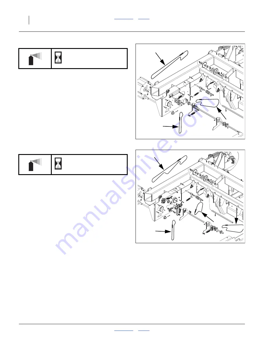
Drive Chains (Single-Hopper)

1 gearbox input chain,

1 gearbox output chain,

1 meter input chain;

3 chains total (see also Contact Drive Chains)
Lubricant: multi-purpose spray lube

Quantity: coat thoroughly

Null4:

Drive Chains (Dual Hopper)

1 gearbox input chain,

1 gearbox-to-meter chain,

1 gearbox output chain,

1 meter input chain;

4 chains total (see also Contact Drive Chains)
Lubricant: multi-purpose spray lube

Quantity: coat thoroughly

Null4:

As Required

Null4:

31179

As Required

Null4:

31185

Summary of Contents for NTA2007HD

Page 1: ...anual NTA607HD or NTA2007HD 6m 20ft No Till Heavy Duty Air Drill Read this manual entirely When you see this symbol the subsequent instructions and warnings are serious follow without exception Your life and the lives of others depend on it Illustrations may show optional equipment not supplied with standard unit Null4 31285 FigureSpacer EN ...

Page 2: ...s and measurements are no longer accurate for your machine Update the record by adding the machine weight and measurements with the option s weight and measurements Null4 aac Null4 aac Dealer Contact Information Null4 aac Model Number Serial Number Machine Height Machine Length Machine Width Machine Weight Year of Construction Delivery Date First Operation Accessories Name Street City State Teleph...

Page 3: ...g Setup 21 Hitching Tractor to Air Drill 22 Hydraulic Hose Hookup 23 Brake Hookup Option 24 Electrical Hookup 26 Heights and Leveling 26 Marker Setup 27 Operating Instructions 29 Pre Start Checklist 29 Master Switch Option 29 Unfolding and Folding 30 Unfold Summary of Steps 31 Fold Summary of Steps 33 Lowering and Raising Air Drill 35 Lowering 36 Raising 37 Transporting the Air Drill 38 Tractor Re...

Page 4: ... Drive Re setting 115 Hydraulic Maintenance 116 Hydraulic Maintenance Safety Information 116 Bleeding Hydraulics 116 In Line Filter 119 Brake Maintenance Option 120 Hand Brake Maintenance 120 Brake Line Charge and Bleed 121 Drain Hydraulic Brake Lines 121 Charge and Bleed System 122 Air Brake Maintenance 123 Reservoir Draining 123 Air Brake Filter Cleaning 123 Brake Drum and Liner Maintenance 124 ...

Page 5: ...l result in death or serious injury This signal word is limited to the most extreme situations typically for machine components that for functional pur poses cannot be guarded WARNING indicates a potentially hazardous situation which if not avoided could result in death or serious injury and includes hazards that are exposed when guards are removed It may also be used to alert against unsafe pract...

Page 6: ...f any links or end fittings are broken stretched or damaged Do not use safety chain for towing Avoid High Pressure Fluids Escaping fluid under pressure can penetrate the skin causing serious injury Avoid the hazard by relieving pressure before disconnecting hydraulic lines Use a piece of paper or cardboard NOT BODY PARTS to check for suspected leaks Wear protective gloves and safety glasses or gog...

Page 7: ...pace With materials loaded or once used for hazardous fertil izers or seeds with hazardous treatments your hoppers may become permit required confined spaces under applicable statutes regulations insurance rules or business policy The vent tube structure in the hoppers has features to assist escape and is not for routine entry A hopper that is full or merely appears full can be an entrapment hazar...

Page 8: ...hrown from the machine Never allow children to operate equipment Keep all bystanders away from machine during operation Transport Machinery Safely Maximum transport speed for implement is 30 kph or 20 mph Some rough terrains require a slower speed Sudden braking can cause a towed load to swerve and upset Do not exceed 30 kph or 20 mph Never travel at a speed which does not allow adequate control o...

Page 9: ...ctrical systems Welding Disconnect battery ground Protect hydraulic lines Avoid fumes from heated paint Inspect all parts Make sure parts are in good condition and installed properly Remove buildup of grease oil or debris Remove all tools and unused parts from air drill before operation Safety At All Times Thoroughly read and understand the instructions in this manual before operation Read all ins...

Page 10: ...ew parts or components also request cor responding safety decals To install new decals 1 Clean the area on which the decal is to be placed 2 Peel backing from decal Press firmly on surface being careful not to cause air bubbles under decal Reflector Slow Moving Vehicle SMV At center of rear caster sub frame cross tube 1 total See Transport Safety Information on page 38 Null4 Reflectors Red Triangl...

Page 11: ...ety Information on page 38 Null4 NTA607HD 833 398C One each side cart front frame one each side rear caster light bar 4 panels total NTA2007HD 833 398C One each side cart front frame 2 panels total Null4 31287 Null4 31103 NTA607HD 838 266C On rear face of reflector support tube under lights outside of Daytime 2 total NTA2007HD 838 266C On rear face of lift assist frame tool bar above Daytime 2 tot...

Page 12: ...f ladders on outside face of casters on bottom forward face of wing pivot weldment faces outward when wings are folded 8 total See Transport Safety Information on page 38 Null4 NTA607HD 838 267C On rear face of reflector support tube near lights inside of Reds 2 total NTA2007HD 838 267C On rear face of lift assist frame tool bar below Reds 2 total Null4 31287 Null4 31286 NTA607HD 838 265C NTA2007H...

Page 13: ...ch 1 total Null4 NTA607HD 848 398C Centered on rear caster sub frame cross tube 1 total NTA2007HD 818 188C On tongue near hitch 1 total Null4 31287 Null4 31234 818 188C Rev C Do Not exceed 20 mph maximum transport speed Loss of vehicle control and or machine can result To Prevent Serious Injury or Death EXCESSIVE SPEED HAZARD WARNING NTA607HD 848 518C NTA2007HD 848 518C Null4 31175 NTA607HD n a Ex...

Page 14: ...p outside faces preset only if markers are installed 0 or 2 total See Marker Operation Option on page 58 Null4 Danger Electrocution On left side of tongue near hitch on sides of cart frame above tires 3 total See Transporting the Air Drill on page 38 Null4 NTA607HD 848 511C NTA2007HD 848 583C Null4 31287 NTA607HD 848 513C NTA2007HD 848 581C Null4 31281 NTA607HD 848 516C NTA2007HD 848 574C Null4 31...

Page 15: ... page 35 Null4 Danger Marker Crush Option On wing outside faces preset only if markers are installed 0 or 2 total See Marker Safety Information on page 59 Null4 Danger Chemicals On each hopper near lid 1 or 2 total See Loading Material Safely on page 47 See Loading Liquid Fertilizer Option on page 50 Null4 NTA607HD 848 523C NTA2007HD 818 624C Null4 31175 NTA607HD 848 528C NTA2007HD 848 580C Null4 ...

Page 16: ...m faces outward when wings are folded 4 total See Unfolding and Folding on page 30 Null4 Danger Marker Pinch Option On upper face at rear of primary marker arm when wings are unfolded Note This is a Haukaas supplied decal and does not need to be replaced if lost damaged or illegible The hazards it refers to are covered by Great Plains decal part numbers 848 513C 848 528C 848 580C and 848 581C Null...

Page 17: ...frame near contact drive on bearing plate near calibration crank shaft on bottom of hoppers above meter input sprocket 4 or 5 total See Calibration Crank Bag and Scale on page 52 Null4 Warning Wear Eye Protection On each hopper at lid walkboard side 1 or 2 total See Loading Material Safely on page 47 Null4 NTA607HD 838 508C NTA2007HD 818 632C Null4 31234 NTA607HD 838 509C NTA2007HD 818 860C Null4 ...

Page 18: ...total See Hydraulic Hose Hookup on page 23 See Hydraulic Maintenance Safety Information on page 116 See Fan Safety Information on page 56 See Weight Transfer Safety Information on page 85 Null4 Warning Confined Space On each hopper at lid walkboard side 1 or 2 total See Hopper Lid Safety Information on page 43 See Loading Material Safely on page 47 See Material Clean Outs on page 111 Null4 NTA607H...

Page 19: ...l4 Warning Pinch Point On outside faces of flex link weldment on outside face of cylinder lug above wing gauge wheels 4 total See Wing Weight Transfer Adjustment on page 88 Null4 Warning Falling Hazard On each side of cart side frame at ladder top 2 total See Ladder Operations on page 42 Null4 NTA607HD 848 522C NTA2007HD 848 576C Null4 31371 NTA607HD 848 525C NTA2007HD 848 578C Null4 31281 NTA607H...

Page 20: ... or 4 total See Setting Material Rates on page 65 Null4 Caution Read Operator Manual On left side of tongue near hitch 1 total Null4 Caution Radar in Use On top side of tongue near radar transceiver 1 total See Minimize Radiation Exposure on page 2 Null4 NTA607HD 848 531C NTA2007HD 818 798C Null4 31195 Null4 31281 NTA607HD 848 512C NTA2007HD 818 630C Null4 31234 NTA607HD 838 506C NTA2007HD 848 577...

Page 21: ...e and Torque On inside face of contact drive wheel arm 1 total See Transport Safety Information on page 38 Null4 NTA607HD 848 497C NTA2007HD 838 092C Null4 31281 838 092C Maximum inflation pressure of tires is 60 psi Torque wheel bolts to 90 105 ft lb To Avoid Injury or Machine Damage from Improper Tire Inflation or Torquing of Wheel Bolts CAUTION NTA607HD 848 498C NTA2007HD 848 102C Null4 31287 8...

Page 22: ...heel arms above tires 6 total See Unfold Fold Safety Information on page 30 See Unfold Fold Safety Information on page 30 See Wing Weight Transfer Adjustment on page 88 Null4 Caution Use Adequate Tractor MetaData End of Safety Decals MetaData End of Important Safety Information NTA607HD 838 507C NTA2007HD 818 398C Null4 31286 Null4 31234 Null4 31281 NTA607HD n a NTA2007HD 848 623C On left side of ...

Page 23: ... pro duction agriculture crops only Do not modify the air drill for use with attachments other than Great Plains options and accessories specified for use with the NTA607 2007HD Drill Using This Manual This manual will familiarize you with safety hitching operation adjustments troubleshooting and mainte nance Read this manual and follow the recommenda tions to help ensure safe and efficient operat...

Page 24: ...your NTA607 2007HD Drill model and serial number here for quick reference Model Number __________________________ Serial Number __________________________ Your Great Plains dealer wants you to be satisfied with your new machine If you do not understand any part of this manual or are not satisfied with the service received please take the following actions Null4 1 Discuss the matter with your deale...

Page 25: ...Setup On initial delivery use with a new tractor and seasonally check and as necessary complete these items before continuing to the routine setup items Bleed hydraulic system page 116 Wing leveling and alignment page 131 Speed sensor calibration DICKEY john Air Cart Con trol manual Blow out entire air system to remove condensation Check air flow at each row for evidence of plugging De grease expo...

Page 26: ...d shut down the tractor If the trac tor draw bar height is incompatible with the drill hitch height move and or invert the hitch to match Hitch Failure Risk The hitch may be mounted inverted if necessary but always have two 2 bolts in two holes of both tongue and hitch See Heights and Leveling on page 26 for hitch adjustments 3 Remove hitch pin Back tractor to align draw bar and drill hitch Shut d...

Page 27: ...an connect the hose under the retracted cylinder symbol to the pressure side of the motor The fan motor further requires hookup of a third case drain line which returns lubricating cooling fluid Marker hoses are provided on the cart even if markers are not installed on the implement See Marker Hose Tips on page 164 prior to first hitching Protecting Fan Hydraulic Motor Seals Low Pressure Case Drai...

Page 28: ... be integrated with the tractor parking brake system Trailer brakes typically are not automatically engaged when the tractor transmission is in Park and may not be engaged by any tractor Emergency Brake Both drill systems include an independent cable oper ated parking brake on the drill The tractor cannot engage or release the drill s parking brake system Braking Hazards Make sure the operator und...

Page 29: ...ing Hazard Do not use the NTA607HD with a single line air brake sys tem This drill is designed for transport speeds that require an air brake system to be dual line A single line tractor sys tem cannot charge the tank that powers the drill brakes Roll Away Hazard When unhitching disconnect the red control line first This sets the brakes on the drill Null4 Hydraulic Brake Hookup Refer to Figure 11 ...

Page 30: ...g problems with uneven depth check air drill levelness and follow these procedures Set Tongue Height Drill must be unfolded for this procedure Refer to Figure 13 1 Complete Bleeding Hydraulics on page 116 2 Unfold the air drill fully page 30 3 Set the initial tongue height tractor hitch and chang ing implement hitch configuration as necessary Dis tance is measured at bottom of hitch to ground leve...

Page 31: ...cylinders stop Only weight transfer adjustment is usually required for wing height although eyebolt adjustment is available When checking tool bar height 1 Move the drill to representative planting soil condi tions 2 Set hitch to planting height page 26 3 Unfold and lower the implement page 30 4 Pull forward a meter or so a few feet to put openers in ground 5 Check tool bar height across air drill...

Page 32: ...28 Great Plains Manufacturing Inc Contents Index NTA607 2007HD 166 283M Contents Index 04 09 2019 ...

Page 33: ...n on page 1 Lubricate as indicated at Lubrication and Sched uled Maintenance on page 134 Check all tires for proper inflation See Tire Infla tion Chart on page 149 Check all bolts pins and fasteners Torque as shown in Torque Values Chart on page 150 Check air drill for worn or damaged parts Repair or replace parts before going to the field Check hydraulic hoses fittings and cylinders for leaks Rep...

Page 34: ...ng in death or serious injury and property damage Falling Hazard Tires Not a Step Do not use tires as steps or platforms All tires can be in light ground contact or free to spin when implement is lowered Wing gauge wheel tires are off the ground in lift Unfold Fold About the Hydraulics The fold unfold and weight transfer functions are on a hydraulic circuit that is shared with the hydraulic fan on...

Page 35: ...h adequate overhead and lateral clearances for the fold operation Unfold Close Fan Shut Off Valve Refer to Figure 17 2 Move the valve handle perpendicular to valve body fan off This valve is located at the front of the seed cart to the left of the hydraulic fan Equipment Damage Risk The fan shut off valve must be closed during unfold and fold operations If the valve is open fan over speed or seal ...

Page 36: ...ng If this operation is not performed the wing openers contact the ground drag and may be damaged The center section lift lock may also fail to release during unfold Unfolding Unfold Wings 7 Unfold the wings by extending the fold cylinders Note One wing may reach the ground before the other It is not uncommon for the folding to be slightly non symmetrical Refer to Figure 20 Hold the circuit at ext...

Page 37: ...not in the wing lock lugs Fold Close Fan Shut Off Valve Refer to Figure 17 on page 31 4 Move the valve handle in Figure 17 perpendicu lar to valve body This valve is located at the front of the seed cart to the left of the hydraulic fan Fold Raise Drill 5 Extend the lift cylinders to full raise drill Hold at raised for a few seconds Set circuit to Neutral Do not install cylinder lock channels Fold...

Page 38: ... sure the lift lock is engaged Lift and re lower if it is not If the lock lug is not fully seated in the lock plate slots it may not engage the pull link lug and the implement will slowly lower after hydraulic power is removed If anyone is working on or under the implement this could result in serious injury or death Null4 Fold Tuck Gauge Wheels Refer to Figure 25 11 Retract the Lift circuit to re...

Page 39: ...if the hydraulic system is damaged They lower rapidly if the hydraulics fail or the Lift circuit is set to Float or Retract Shoving Hazard Air drill length changes by 56 cm 22in during raising and lowering Injury is possible Implement casters and row units move forward during raising and backward during lowering Gauge wheels move forward during lowering Casters may swivel Tractor may move in some ...

Page 40: ...res when implement is lowered Wing gauge wheels caster wheels and seed cart wheels may have little or no weight on them and may turn suddenly and without warn ing if used as a step resulting in serious injury Null4 If lock cylinder is extended check that the fan shut off valve is closed page 31 then perform a brief unfold operation Extend the Fold Fan circuit to retract the lock cylinder If the lo...

Page 41: ... field turns the center section lift lock does not automatically engage during lift The lock does automatically engage during full fold To engage the lock without folding follow these additional steps Refer to Figure 29 5 Verify that all persons are safely clear of implement sections 6 Close the fan shut off valve page 31 7 Have an observer stand where the observer can see the lock cylinder and th...

Page 42: ...unfold to ground contact or implement can settle into ground contact Loss of Control Hazard Tires Inflate tires to factory specifications Tighten wheel nuts to specifications Under inflated tires or loose nuts can cause loss of control Over inflated tires or overt tightened nuts can fail suddenly and cause loss of control Loss of control can cause a major accident resulting in death injury and equ...

Page 43: ...s equipped with optional brakes With tractor in Park and with tractor parking brake set release drill parking brakes page 40 Always have lights on for highway operation Comply with all national regional and local safety laws when traveling on public roads Release all brakes and travel with caution Typical NTA607 2007HD Drill Weights Null4 Null4 31153 Material may be loaded prior to travel but incr...

Page 44: ...braking is released shortly after unhitching the cart Parking Brakes Cable operated parking brakes engage and release independently of the service brake system There is one operating handle inboard of each cart transport wheel The parking brakes themselves are independent sys tems for each side of the cart None of these three brak ing systems can engage or release any of the others Refer to Figure...

Page 45: ...ylinder The drill brake hydraulic lines are separate from the tractor s line With the hydraulic hydraulic system braking is immedi ately available when the tractor hydraulic system is active Dual Line Air Hydraulic Brake Operation In this system the supply yellow or blue coded line charges a reservoir air tank on the drill The service red coded line meters air from the reservoir to a booster cylin...

Page 46: ...ed ladders may not meet highway clearance requirements that apply to your operations Deploying Ladder Refer to Figure 35 1 Use one hand to hold the ladder up while pulling horizontal pin to the right Refer to Figure 34 2 Carefully swing ladder out and down Using Ladder 1 Ascend and descend the ladder while facing the drill 2 Use the handrails when on the higher steps Raising Ladder 1 Swing the lad...

Page 47: ...are especially danger ous When hazardous fumes or low oxygen levels are present you can be quickly overcome even in an empty hopper with the lid open There may be no odors to alert you to the haz ard Blowing Debris and Inhalation Hazards Turn off fan before opening hopper lids Wear eye protection and dust mask or respirator Hoppers are mildly pressurized and air is circulating in the hopper when t...

Page 48: ... inspect the hopper itself 7 If the strainer needs to be removed for cleaning do not perform these steps until immediately ready to clean the strainer and return it to the hopper Lid Closing Refer to Figure 37 1 Swing lid over opening until capture hook is cen tered on U bolt shackle 2 Open handle and engage hook on shackle 3 Close handle for operations or short term parking For long term storage ...

Page 49: ...is vented and will be releasing vapor from the tank At higher inlet rates the tank may also be mildly pressurized and removing the lid could expose you to sudden high concentrations of vapor Refer to Figure 38 Wear chemical gloves The underside of the lid is likely to be damp or wet and coated with whatever chemicals have been used Wear a mask or respirator Consult the MSDSa for the materials rece...

Page 50: ...ill swing down on its own If not pull it open by hand Meter Door Closing Make sure the clamp handles are out or down not up or it will not be possible to close the door 1 Use a clean rag to wipe any residual material from the face of the elastomer seals on the door and from the bottom face of the meter box 2 Swing the door up into closed position 3 While holding the door closed swing one clamp han...

Page 51: ...ith the hopper lid open Agricultural chemicals can be dangerous including treat ments on seeds and components of fertilizers Improper use can seriously injure persons animals plants soil and prop erty Read and follow chemical manufacturer s instructions Wear protective clothing Handle all chemicals with care Avoid inhaling smoke from any type of chemical fire Store or dispose of unused chemicals a...

Page 52: ...alfway point for meter change over However avoid simultaneous metering if it would result in a Low Range variable rate gearbox set ting below a scale value of 20 If metering simultaneously set each meter for one half the chart or calibrated rate Do not merely use half the single meter scale setting as this is usually not half the rate See Setting Material Rates on page 65 and the Seed Rate Manual ...

Page 53: ...ainer periodically for foreign matter If markers are not installed on the implement circuits A B are available at the left rear of the cart and may be used for auxiliary purposes such as a user provisioned auger Auger height required is 3 0m 9 8 ft for 5290 liter 150 bu hopper and 2 8m 9 3 ft for 2890 liter 82 bu hoppers Loading Close Out 16 Remove any foreign matter from the strainer basket 17 Wi...

Page 54: ...izer system do not include agitators Tank Loading All Methods Tank fill level is reported by a sight gauge on each tank The table at right converts the scale levels to liters Refer to Figure 44 on page 51 and Figure 146 on page 163 1 Hitch cart and set tractor parking brakes If filling unhitched make sure that tongue jack is on an ade quate surface Block cart tires or set optional cart brakes 2 Cl...

Page 55: ...alve 15 Stop the source pump if any Close the cart inlet shut off valve if not already closed 16 Unless already at the field close both tank discharge valves to prevent tank to tank transfers during transport Tank Loading Top Fill Complete step 1 through step 7 on page 50 17 Deploy the ladder s as needed for access to the tanks page 42 Refer to Figure 45 18 Unscrew the lid on the tank to be filled...

Page 56: ...the counter clockwise direction Operating in reverse can damage the meter gear box and produces low sample sizes leading to incorrect calibration and excessively high field rates Operating the Hand Crank 1 Turn on the seed monitor This step is required if the Variable Rate option is installed 2 Raise drill page 37 This prevents the contact drive wheel from engaging the transport tire Note Although...

Page 57: ...chute latching slots 9 Turn the crank until material is flowing to the bag Stop Sweep any material in the chute into the bag Empty the bag 10 Turn the hand crank counter clockwise to simulate meter operation for 1 10ha or 1 10ac Specific recommendations may be made in applicable manual sections See see Meter Calibration in the Seed Rate manual see Unloading Materials on page 110 and see Storage on...

Page 58: ...ntents Index 04 09 2019 Air System Operation Null4 aac Null4 Null4 Figure 51 Single Hopper Air System 31324 1 2 4 5 6 8 9 7 10 11 12 14 15 16 17 18 19 Null4 Figure 52 Dual Hopper Double Shoot Air System 31325 1 2 3 4 5 6 8 8 9 9 7 10 11 12 13 14 14 15 15 16 16 17 17 18 19 20 ...

Page 59: ...encoder provides metering rate data stop page alarms and is used by the optional Variable Rate Kit to control metering rate 12 Meter Outlet Ports Material falls from the meter flutes into the air streams flowing from inlet manifold to outlet ports Each port is a separate compartment 13 Single Shoot Y Tube A two hopper drill may optionally have the output of both meters combined into a single strea...

Page 60: ...is type of injury Machine Damage Risk Protect Motor Seals Fan circuit has three hoses All must be correctly connected Make sure that SUMP line is connected to a tractor port capable of accepting high volume low pressure return oil Connect Case Drain line to a low volume case drain return Avoid sudden circuit changes Motor seals may be damaged by rapid starts and stops or by circuit reversals Engag...

Page 61: ...ay observe some minor fluctuation in fan rpm as the implement circuits demand oil see decal right panel The fan must be shut off during fold and unfold operations page 30 The fan must be off for calibration page 52 The fan may be on when the implement is folded and locked page 33 for air system clean out page 111 Machine Damage Risk Always engage the fan with the tractor at a low engine speed Enga...

Page 62: ...e blades coast to a stop Marker Operation Option Dual markers are optional on the NTA607 2007HD See Markers on page 144 for ordering information Additional Marker Topics See also Marker Adjustments on page 96 and Marker Maintenance Option on page 132 Dual markers are on a dedicated hydraulic circuit which contains an adjustable automatic sequence valve Marker circuits must be fully charged with oi...

Page 63: ...sides of the drill 2 Carefully move the circuit lever to extend and observe which marker side is extending Refer to Figure 55 3 If the marker extending is not on the desired side reverse the lever to retract until the marker returns to the cradle Set the control to Neutral briefly then to Extend again This cycles the sequence valve and extends the alternate marker 4 When marker is fully extended s...

Page 64: ...er doors closed 46 Manifold to hopper seal Materials loaded 47 Hose routings no sags no pinches check wing folded field positions Hoses fully connected to meters towers and openers Frame Mounted Coulter Checklist Page Coulter blade wear 89 Coulter to row alignment 89 Coulter down force 90 Row Units Checklist Page Preset depth handles alike 95 Preset down force springs alike except in tracks 92 Che...

Page 65: ...s can result in excess meter oscillation as hoppers near empty First Pass Operation Checklist Page 1 Drill unfolded and aligned for first pass with opener disks about 3m 10ft before field edge 30 2 Run fan for at least 15 minutes before planting 3 Unfold marker on next row side 4 Set fan hydraulic circuit to low flow engage circuit Gradually adjust fan hydraulic flow to obtain 3800 rpm 82 5 Check ...

Page 66: ...to Air Drill on page 22 5 If ground is soft place a wide block or plate under the jack to increase contact area 6 Securely block drill tires to prevent jack from digging or sliding off plate 7 If drill is equipped with optional brakes set the park ing brake handle on each side of the drill For dual line air brakes disconnect the red control gladhand connector first at the tractor then the blue sup...

Page 67: ...s listed under Lubrica tion and Scheduled Maintenance on page 134 9 Check all bolts pins fittings and hoses Tighten repair or replace parts as needed 10 Check all moving parts for wear or damage Make notes of any parts needing repair or replacement before the next season 11 Open the meter box doors completely to release seal pressure and allow rinse water to exit 12 Thoroughly wash the hoppers wit...

Page 68: ...ce is Seed Rate manual 167 085B High Rate Flute Sets 65 150 or 200 metering rates Rate Range Gears 71 10x metering rate change Variable Rate Gearboxes 72 0 to 100 of current rate range Calibration 73 Correcting chart rate to your specific materials Marker Adjustments Marker Extension 97 Intended swath spacing Marker Tension 96 Marking weight Correct folding Marker Disk Angle and Direction 98 Visib...

Page 69: ...rtilizer See page 149 Always replace worn tires with the correct size Check Flute Shaft Configuration For some unusual rate applications Great Plains offers optional meter flute shafts page 143 that can increase rates to 150 or 200 of factory standard Refer to Figure 58 which depicts a single flute star with its halves a single star mated two stars staggered and a filler Know your stars setup If y...

Page 70: ...ent mate rials at the same time treat them as single hopper oper ation High Rate Flute Considerations High Rate charts are provided for some seeds but the charts do not cover all possible combinations of high rate flutes You can use any standard rate single hopper chart Adjustment for Dual Metering High Rate Flutes To find the initial chart rate for dual hopper and or alter nate flutes anchor To f...

Page 71: ... plier If unknown use the value from the rate chart Number of Outlets per Meter or Total Number of Towers This is the number of primary hoses coming off a single meter box this is always 4 for NTA607 2007HD whether single or double shoot Calibration Constant This is the number listed in the seed rate charts for the rate you are planting or the num ber obtained by calibration for your specific seed...

Page 72: ...r is a handy tool for fine tuning the variable rate gearbox set ting If the rate reported by the monitor does not match the desired planting rate rotate the crank to adjust the variable rate gearbox control arm slightly so as to achieve the desired planting rate GRAN SEED CONTROL GRAN FERT CONTROL Update Material Library In order to correlate actuator output with desired seed rate meter shaft rate...

Page 73: ...he same name as the material name setup on page 68 In this example Wheat 2S the 2S refers to the factory standard 2 star meter flute configuration Pick a seed constant closest to yours in terms of physical seed characteristics and meter flute config uration If a suitable Variable Cal Const is available the sys tem can more accurately compensate for manual calibration cranking speeds that differ fr...

Page 74: ...or 2 Per meter being config ured Type GRAN SEED CONTROL or GRAN FERT CONTROL One of these Required Material Name Wheat HRW or 11 52 0 Example user speci fied names Control Mode Auto Required Drive Type Zero Max 1 or 2 Required Drive Freq 40 Hz Required Input Fliter 50 Required Sensor Constant 360 PUL REV Required Gear Ratio 1 0 Required Meter Gear Range LOW or HIGH One of these Required Seed Rows ...

Page 75: ...e which is used for smaller seeds and lower seeding rates The meter shafts are DRIVING and DRIVEN The DRIVING shaft is the upper agitator shaft The DRIVEN shaft is the lower flute shaft Refer to the Seed Rate chart or Fertilizer Rate chart the table at right and Figure 60 for setting the seed meter final drive range 1 Remove the nut and bolt not visible securing the application rate sensor to the ...

Page 76: ...eed Rate chart or determined by calibration 4 Reinsert the hairpin cotter Variable Rate Servo Rate Setting 1 Consult the seed rate chart for your crop flute stars and rate Range Note the Cal Const 2 Enter the chart Calibration Constant on the seed monitor for the Channel associated with the hopper and gearbox If you have calibrated this seed use the recorded Cal Const developed from that cali brat...

Page 77: ...t gearboxes These first steps are common to both gearbox types The right column contains an example for the following steps 1 Raise drill page 37 This prevents the contact drive wheel from engaging the transport tire 2 Turn on the seed monitor 3 Determine the Range and gearbox settings from the rate charts 4 If your material has a density that is significantly dif ferent from that used to generate...

Page 78: ...with an adequate air seal Refer to Figure 63 note Figure exaggerates size of cranking directional decal 10 Attach crank page 52 Un pin crank from storage location and place over hex shaft at cranking loca tion right side of cart between rear most gearbox and transport wheel 11 Weigh bag page 53 Obtain the calibration sample bag and digital scale from the storage compartment Zero the scale and weig...

Page 79: ...o compute the Calibration Constant The Meter Revs parameter is used for a progress bar displayed during calibration 20 Turn the hand crank counter clockwise to simulate meter operation for 1 10ha or 1 10ac See table at right Note It is important to turn the calibration crank rapidly Use a comfortable speed of 1 to 13 4 revolutions per second which simulates a planting speed range of 6 7 11 8 kph 4...

Page 80: ... a correction differ ence Null4 27 Refer to the seed rate chart for Seed Rate gearbox setting values for the target rate Null4 Manual Seeding Example Net Weight step 23 TotalWeight is 20 96 kg for bag plus sample BagWeight is 0 91 kg SampleWeight is 20 96 0 91 which is 20 96 kg SampleWeight TotalWeight BagWeight If the calibrated rate turns out to match the desired tar get rate record the material...

Page 81: ...ly calibrated re mount the final drive gear removed if any from the meter on the other hopper 32 Repeat the calibration procedure for the other hop per starting at step 1 on page 73 33 Continue at Calibration Closeout on page 79 TargetRate Null4 Metric Example Initial Variable Rate Gearbox Setting 62 163 7 183 5 59 78794 169 0 189 4 60 78916 174 3 195 4 61 79050 179 6 201 3 62 79197 185 0 207 4 63...

Page 82: ... revolutions cranking rate and precise starting and stopping handle angles are not critical as the system reads meter revolutions accu rately and can compensate for shaft speed seed size and partial turns What matters is getting a large sample to reduce errors and increase confidence in the calibration Note By calibrating at or near target rate and for 1 10ha you establish a comfort level that the...

Page 83: ...pplication rate for 1 10 hectare or 1 10 acre 40 Press the Stop softkey on the monitor and enter the sample net weight SampleWeight The monitor responds with a Calibration Constant Push the Save softkey to accept this value Calibration Closeout 41 Wipe the calibration door seals Close the calibration door s Raise and latch the chute See page 46 42 Re install any removed final Range gears 43 Remove...

Page 84: ...ust ment to accurately set wing gauge wheel height In more challenging conditions increased cart weight transfer page 85 may be required to prevent openers from lifting tool bar 4 Wing Weight Transfer page 85 If the wings are not operating at desired planting depth more center section weight may need to be transferred to wings 5 Coulter Depth option page 89 Optional coulters prepare the furrow ahe...

Page 85: ...a minimum tool bar height of 58 4cm 23 0in All spacer combinations that increase tool bar height above the minimum must be a stack of at least 5 7cm in height Note Each full 1 cm or 1 inch of spacer stack height change changes the tool bar height by 2cm or 2in Note Do not use a spacer stack taller than 10 2cm 4 0in or the furrow will be too shallow or there will be no furrow at all Null4 Figure 66...

Page 86: ...mage Do not reverse hydraulic flow with the fan run ning At ideal fan speed flow is more than high enough to avoid blockages from both meters on dual hopper drills flow is even across all hoses from each meter and flow is low enough to minimize seed cracking and bounce Fan speed is monitored and reported by the seed moni tor but is manually controlled If the fan cannot reach 3000 rpm one or more h...

Page 87: ...rn 2 Watch the manifold pressure gauge s and seed monitor and adjust fan speed by increasing or decreasing hydraulic flow from the tractor Use the guidelines and the fan speed chart on page 82 to properly adjust fan speed Fan Speed Tips Higher fan speeds improve seed distribution but high fan speeds also increase the chance of seed damage and bounce At first adjust fan speed to the high end of the...

Page 88: ...neven flow such as block age pressure alarms and seed cracking bounce 3 Adjust fan rpm up and down until you discover the upper and lower rpms that represent the optimal working range for each meter Note the upper and lower the manifold pressures for that operating range The ideal median pressures for each meter are likely to be different 4 If there is no single fan speed that puts both meters com...

Page 89: ...all bystanders well away You will be seriously injured or killed if you are caught between lowering openers and ground or raising openers and drill frame High Pressure Fluid Hazard Escaping fluid under pressure can penetrate the skin causing serious injury Use a piece of paper or cardboard NOT BODY PARTS to check for suspected leaks Wear protective gloves and safety glasses or goggles when working...

Page 90: ...for no oil flow by turning knob on valve clockwise completely Always operate the drill with the bypass valve closed Tractors with Load Sensing Closed Center Hydraulics LS Closed or Pressure Flow Compensating PFC Systems The weight transfer bypass valve must be adjusted to protect the tractor Do the following procedure Equipment Damage Risk Failure to use the bypass valve on load sensing tractors m...

Page 91: ...ld cylinders distribute center section weight to the wings The wings are much lighter than the center section so some weight needs to be transferred The wing transfer valve controls the amount of weight transferred The wing transfer valve needs an initial setting and possible later adjustment If insufficient weight is transferred the wings run higher than the center section If excess weight is tra...

Page 92: ...ent 1 Release lock ring on cart transfer valve Adjust knob while observing gauge 2 Increase weight transfer from cart by turning knob clockwise Reduce weight transfer from cart by turning knob counter clockwise 3 Set pressure to at least 100 psi 4 Secure setting with lock ring Testing Weight Transfer Adjustments 1 Pull forward in ground Assess opener penetration and coulter option penetration Comp...

Page 93: ...rows may be lowered by loosening nuts at tool bar U bolts sliding the spring bar down and re tightening Do not lower more than about 1in 2 5cm Keep the top edge of the spring bar at or above the top of the upper bolt holes 3 Individual coulter down force page 90 This is a spring adjustment for rows in tracks or all rows in unusually light or heavy no till conditions 4 Coulter to row alignment Coul...

Page 94: ...de up over obstructions To adjust the coulter spring Refer to Figure 76 1 Unfold implement Configure implement for mainte nance lift lock page 107 2 Determine the new spring length desired See the table at right 3 Measure the current length of the spring s to be changed If already shorter than 24 8cm 93 4in or longer than 26cm 101 4in do not further adjust them 4 Loosen the jam nut 5 Rotate the ad...

Page 95: ...r II on single shoot drills No adjustments are necessary 5 Inside Scraper optional Helps prevent clogging between disk blades See Disk Scraper Adjustments on page 93 6 Liquid Fertilizer Tube optional This is present only if both a liquid fertilizer system and Keeton seed firmers are installed It requires no adjustment 7 Seed firmer seed flap not shown standard A seed flap requires no adjustment ot...

Page 96: ...stagger is not adjustable but disk to disk spacing is and may need attention as disks experience normal wear Spacers will need to be reset when blades are replaced Refer to Figure 79 The ideal spacing causes the blades to be in contact for about 2 5cm 1 inch If you insert two pieces of paper between the blades the gap between them should be 0 to 4 4cm 0 to 1 75in If the contact region is significa...

Page 97: ...side to the outside Note When installing new blades it is generally neces sary to move outside spacers back inside after both disks are mounted 4 Re assemble and check disk contact Disk Scraper Adjustments Disk scrapers are optional See page 145 ordering infor mation and page 166 for installation To keep opener disks turning freely dirt scrapers are mounted between disks to clean as disks rotate S...

Page 98: ...lides down the seed trench It traps seeds as they exit the seed tube and firms them into the bottom of the V Refer to Figure 82 The Firmer is provided with a preset tension which is rec ommended for using the first year The tension screw can be tightened in subsequent years according to your needs Firmers should provide just enough tension to push seeds to the bottom of the trench Seed Lok Seed Fi...

Page 99: ...ess wheels to the same height Each increment of the handle adjusts the seeding depth by approximately 6 3mm 1 8in The range is approximately 0 8 9cm 0 to 31 2in seeding depth For more shallow seeding slide T handles forward toward implement For deeper seeding slide T handles backward away from implement If moving the T handle backward doesn t cause the opener to achieve desired depth lower the cou...

Page 100: ...djust able and may be used to increase or decrease force at the marker disk The suggested initial marking force is 23 kg 50 lbs For marking forces up to this value use the scale included with the drill to lift the extended marker disk To adjust the marking force 1 Fold the markers page 58 This minimizes spring tension for adjustment 2 Set the marker hydraulic circuit to Neutral Shut off the tracto...

Page 101: ...ut another way increases the swath averaged row spacing of the drill The table at right presumes that the pass gap is set to the nominal row spacing for all models It shows the actual swath for both wing types and effective row spac ing for higher down flex drills For most accurate seed monitoring use the Swath and Avg Spcg data at right To change marker extension on a lowered drill Refer to Figur...

Page 102: ...hifting the bracket which has slotted holes Re align the guard with the disk edge Tighten the nuts Re check marker extension 2 For a larger change in mark angle the bracket has a choice of small slotted holes on one side Loosen both nuts Remove the bolt on the two hole side Re insert the bolt in the alternate hole Re align the guard with the disk edge Tighten the nuts Re check marker extension 3 M...

Page 103: ...n running backward Reverse fan circuit hoses at hitch No material flow multiple rows Primary seed hose blocked Check seed hoses for kinks congealed materials at low spots nests and pests Tower inlet or turret blocked No material flow one or two rows Seed tube blocked at row Inspect and clear seed tube Tower port blocked for affected row Disassemble distribution ring and clear blockage False alarm ...

Page 104: ... Inflate low tires Fan speed too low Increase fan speed page 82 Fan won t run fast enough Tractor must be able to supply 18 gallons minute at 200 psi Fan won t run fast enough Check that hydraulic fan check valve is not installed backward Actual field size is different Verify field size Excessive bout pass gaps Irregular shaped field Adjust marker page 97 Build up of treatment or debris in seed me...

Page 105: ...eed tube Lift up drill expose bottom of seed tube and clean out Hectares or acres planted not correctly reported Area tally is most accurate when seeding back and forth with markers with few headlands and curves Incorrect tire size or air pressure Correct tire size or air pressure page 149 Excessive overlap or gaps between passes Avoid overlap or gaps Adjust marker Soil conditions Loose soil and s...

Page 106: ...too high and not allowing disk to drop into field depressions or mark on flat ground at extreme spring settings Reduce counterbalance spring force Disk orientation not ideal for conditions Reverse marker disk to pull or throw dirt Chain Skipping or Excess Wear Debris no retainer clip Be sure retainer clip is facing in opposite direction of chain travel page 108 Excess slack Adjust chain slack page...

Page 107: ...eed system Air Hydraulic system damaged diaphragm in booster chamber Replace booster Air Hydraulic system leaks in air system Repair leaks Air Hydraulic system clogged filters Clean filters page 123 Air Hydraulic system valve open Close dump valve page 125 Close petcock page 25 Hydraulic Hydraulic system air in brake line from tractor Bleed and recharge brake line Brake linings and or drums worn S...

Page 108: ... psi Minimum required air pressure is 550 kPa 80 psi Dragging brake Over extended adjuster Reset adjuster Inspect to discover why it overextended Debris in brakes Remove brake shoes Clean and dry Distorted brake parts scraping Replace damaged parts Weak return spring Replace all springs Piston seized in brake cylinder Rebuild or replace cylinder Ice in parking brake lines Warm and release lines Ch...

Page 109: ...er s viewing position MetaData End of Troubleshooting Problem Cause Solution Non zero with fan off Zero drift Re zero per instruc tions below Gauge reading lower than expected Relief port plug missing damaged Replace plug Breather line blocked or kinked Clear breather line Leak in sensing line Check line to cham ber Gauge damaged Check for loose cover damaged O ring 0 10 30 20 40 50 1 Null4 Figure...

Page 110: ...in Check all hydraulic lines and fittings before applying pressure Fluid escaping from a very small hole can be almost invisible Use paper or cardboard not body parts and wear heavy gloves to check for suspected leaks If injured seek immediate medical attention from a health care provider familiar with this type of injury After using drill for several hours check all bolts to be sure they are tigh...

Page 111: ...mplement sections at raised for mainte nance and for raised unfolded storage The gauge wheel lock channels are not used in routine operations field or transport Steps to engage maintenance lift lock presume a starting configuration of implement unfolded and lowered 1 Raise the unfolded implement Refer to Figure 92 2 Install the gauge wheel lock channels Remove the channels from the wing lugs and p...

Page 112: ...ing stored at the end of the planting season Chain Slack Refer to Figure 95 which for clarity greatly exaggerates slack and omits the idlers 1 Measure the span for allowable slack Locate the longest span of each chain usually the span which does not run through the idlers 2 Determine the ideal slack Long chains over 91cm 36in 2 1cm m 1 4in per ft Vertical short chains 2 1cm m 1 4in per foot Horizo...

Page 113: ...enerally not necessary to remove the plug although doing so may ease cleaning of the canister Make sure the plug is tight when re installing 3 Wash the filter cartridge with water or replace with new cartridge if necessary Inspect the screen and O rings for damage A new cartridge includes cartridge O rings 4 Inspect the large O ring on the canister Replace as necessary 5 Reinstall the cartridge ca...

Page 114: ...pen Clean Out door second and if using an auger have a second person start the auger as soon as the first person is clear Expect material to flow in significant volume until the hopper is empty Inspect the hopper from the lid to confirm that it is empty 10 Install the calibration crank page 52 Rotate it until no material flows from the calibration door 11 Shut down and withdraw auger if used 12 If...

Page 115: ...Prob lem Clean Outs on page 112 5 Install the calibration crank Open both calibration and clean out doors on the meter of the hopper to be cleaned out 6 Power wash the interior of the hopper while a second person cranks the meters page 52 7 Re install strainer Close lid tight and secure handle 8 After cleaning out the last hopper close all doors Run air system for 10 minutes to blow moisture out o...

Page 116: ...y The hopper vent tube structure includes features to aid emergency egress It is not intended for routine entry However do not remove the vent tube structure as it is required for pressure balancing the air space above the material Depending on their use the NTA607HD or NTA2007HD material hoppers may be or become permit required confined spaces under U S OSHA regulations 29 CFR 1910 146 and simila...

Page 117: ...hopper 4 Equip the team At least one attendant must be equipped with com munications capability to summon outside aid in the event that the hopper worker is overcome Equip the entrant with a safety harness and safety line 5 Train the team Review the hazards Review the procedures Under stand the use of the protective equipment Know the steps to take in emergencies Practice them Train the observer t...

Page 118: ... Securely support center sec tion tool bar at this height with jack stands or blocks Loosen switch pivot screws Adjust switch angle so that toggle is level or slightly tilted up to the right Loosen bracket bolts and slide switch up or down until the flexible switch toggle is just past the point at which the switch is activated flexible switch toggle deflected up Note The implement lift switch has ...

Page 119: ...ient traction between the contact drive tire and the main transport tire or excess spring force at contact tire check tire sizes and inflation page 149 Use tire sizes specified by Great Plains at recommended pressures Do not attempt to compensate for worn under inflated or incorrect tires by adjusting spring tension Null4 If any spring assembly components are replaced the factory settings for spri...

Page 120: ...e Persons Required Bleeding is not a single person operation Establish a signal ling protocol between the tractor cab operator and the observer at the bleed points Establish an emergency stop sig nal Determine the safest stop mode for each bleed Where components cannot move down suddenly setting the circuit to Float can relieve pressure in lines depending on valve set tings Where components repres...

Page 121: ...e and save the spacers to prevent the cylinders from resting on the spac ers 3 Lower the implement If the lift cylinders bottom out on the rod ends it will be necessary to use jacks or stands under the tool bar Raise the implement Lower it on the supports 4 Set the Lift circuit to Float Shut off tractor Remove key 5 Unpin the rod ends of both center section lift cylinders and both wing gauge wheel...

Page 122: ...d center lock cylinder rod 6 Loosen the JIC fittings at the base end of both fold cylinders the base end of both transfer cylinders and at the rod end of the lock cylinder 7 Slowly extend the circuit same direction as fan oper ation until fluid appears at each loosened fitting Set circuit to Neutral and secure each fitting in turn Repeat until all five fittings are secured 8 Continue to Extend cir...

Page 123: ...own tractor and remove key Refer to Figure 107 4 Slowly loosen filter and relieve any residual pressure in line When disconnecting hose support the end to minimize fluid loss 5 To disassemble unscrew end cap of filter Remove top retaining washer and screen 6 Clean filter screen with solvent and compressed air or replace if needed 7 When reassembling put screen into filter Place retaining washer on...

Page 124: ...enance Hand Brake Maintenance Refer to Figure 108 Periodically adjust the setting of the handle knob so that the handle snaps firmly into place as brakes are engaged If the handle runs out of adjustment or is close to run ning out of adjustment loosen jam nuts and re position the brake end barrel on the cable casing Further adjustment is available at the barrel on the handle end of the cable casin...

Page 125: ...nder movement 3 Put tractor in Park Refer to Figure 109 which depicts hydraulic brake system reservoir for air brake system is similar 4 Clean and dry top of master cylinder reservoir 5 Remove cap and keep free of contaminants Drain Hydraulic Brake Lines 6 If draining brake system A Remove drain plug at rear of reservoir and empty reservoir Re secure plug B Start the left hub for the following ste...

Page 126: ...ep full 11 When fluid appears at valve close valve 12 Repeat step 9 through step 11 for the right hub Null4 Refer to Figure 114 13 At brake line tee loosen center port connection just enough to allow air to escape when system is pressurized but not enough to allow air to enter 14 Cycle tractor brakes until no air bubble appear at connection Tighten connection 15 Top off master cylinder reservoir E...

Page 127: ...ox end wrench 3 Carefully remove the cap from one filter Be ready to catch the filter screen when it falls free Null4 aac anchors table image Note The inside diameter of the screen is the inlet side The screen is entirely welded stainless steel 4 Using gentle compressed air or a soft brush and compatible cleaning fluid remove debris from the screen Dry thoroughly 5 The cap is a debris sump Clean i...

Page 128: ...moval of the wheels through shop cleanup after completion of brake work including empty ing vacuums changing HEPA filters and rag disposal Procedures for Servicing Brakes Service the removed brake assembly in a negative pressure enclosure The enclosure should be equipped with a HEPA vacuum and worker arm sleeves With the enclosure in place use the HEPA vacuum to loosen and vacuum residue from brak...

Page 129: ...t at the braking surface of the drums 9 Remove wheels If you have more than one wheel removed at a time mark on them where they came from L R and inside outside as the tire tread pat tern is directional Refer to Figure 119 10 Remove hub drum assembly Remove the dust cap Remove the spindle cotter pin Remove the spindle nut Remove the spindle washer 11 Carefully pull hub and drum assembly from spin ...

Page 130: ...necessary disassemble adjuster for cleaning Inspect adjust pawl and rack for wear and damage Great Plains recommends replacing the entire adjuster if any parts are worn or damaged 21 Apply thin film of Lubriplate 110 or similar to self adjuster Brake Slippage Hazard Do not allow any lubricants to come in contact with new brake linings 22 Release upper spring between shoes was under self adjuster a...

Page 131: ... force 31 Remove large flat washer 32 Remove hold down bolts and brake shoes 33 Inspect brake shoes Check that web is flat and at a right angle to table Check welds for cracks Check operating holes for wear and peening If any defect or damage is noted replace shoes regardless of lin ing status 34 Replace any shoes contaminated with oil 35 If replacing one shoe set due to normal wear Great Plains r...

Page 132: ...plate studs through dust cover and spindle weldment Secure with lock washers and 1 2 13 nuts Re Install Springs Refer to Figure 124 40 With link arm toward front of cart insert parking brake arm assembly from spindle side of backing plate through lower slots in brake shoes 41 Insert double bend end of parking brake spring in hole at rear end of parking brake arm Hook single bend end at small notch...

Page 133: ...ing seals carefully align them so they are concen tric with the shaft hole Apply insertion force across the entire face or at least equally along the entire outside diameter as close to the seal O D as possible Seals are hollow metal structures and are somewhat fragile The are not intended to be in contact with the bearings 51 Carefully place drum hub assembly on spindle 52 Insert re packed outer ...

Page 134: ... the tractor in Park but release any brakes that operate the trailer ser vice brakes 61 Have someone spin one brake equipped cart wheel and stand clear 62 Slowly engage the tractor service brakes If the wheel does not stop spinning this may merely indi cate that the self adjusters have not yet seated Cycle a second time 63 Check for unusual noises and failure to brake Check that the wheel spins fr...

Page 135: ...se checks before con sidering any adjustment to the eyebolts 1 Page 117 Is the lift system charged and bled If there is any air in the system the wing heights may not track the center height or each other 2 Page 117 Is the lift system re phased If the wing cylinders are not tracking the center cylinders per form a re phase 3 Page 149 Check tire inflation 4 Page 88 Is weight transfer properly set f...

Page 136: ...rker Hydraulic Bleeding 1 Review warnings bleeding notes and system infor mation on page 116 Refer to Figure 131 2 With markers unfolded in field position crack hydraulic hose JIC fittings at base and rod ends of each marker cylinder 3 With tractor at idle speed activate tractor hydraulic valve forward until oil appears at a fitting When oil begins to seep out around a fitting tighten that fitting...

Page 137: ...o Figure 132 To replace a seed flap use a needle nose pliers or similar tool to grasp T top of flap Pull upward to pull flap up out of metal bracket Push new seed flap down through metal bracket until flap snaps into place with T top resting on top of bracket MetaData End of Chain Maintenance Null4 Figure 132 Seed Tube Flap 31047 2 1 1 2 1 2 ...

Page 138: ...lex Pivots 1 zerk each wing pivot arm 2 arms per wing 4 zerks total Lubrication multi purpose grease Amount until grease emerges Null4 Marker Tilt Bearings Option 2 zerks each marker pivot frame 4 zerk total Lubrication multi purpose grease Amount until grease emerges Null4 0 1 10 50 50 Multi purpose spray lube Multi purpose grease lube Multi purpose oil lube Intervals operating hours at which ser...

Page 139: ...2019 Contents Index 166 283M Cart Implement Link 1 zerk at each arm tube end 4 total Service rear zerks from access ports under tubes Null4 Rear Lower Parallel Arms 1 zerk at each arm tube end 4 total Service rear zerks from access ports under tubes Null4 10 Null4 31238 10 Null4 31259 ...

Page 140: ... per grease bank 3 grease banks per implement 32 or 40 zerks total Lubrication multi purpose grease Amount until grease emerges Note These zerks only serve the coulter pivots Coulter hubs are lubricated at the hubs Null4 Fertilizer Pump Bearings Option 4 zerks total Lubrication multi purpose grease Amount until grease emerges Refer to CDS JohnBlue pump manual for pump mainte nance Null4 10 Null4 3...

Page 141: ... contact drive tire 2 cart tires 4 gauge wheels Check tire pressures more frequently on a new drill and with new tires Check tire pressures whenever there are planting problems Null4 Contact Drive Chains 2 chains remove cover for access to wheel arm Lubrication multi purpose spray lube Amount coat thoroughly Null4 10 Null4 31241 1 2 1 2 20 848 102C Maximum inflation pressure of tires is 40 psi Tor...

Page 142: ...ain 3 chains total see also Contact Drive Chains Lubricant multi purpose spray lube Quantity coat thoroughly Null4 Drive Chains Dual Hopper 1 gearbox input chain 1 gearbox to meter chain 1 gearbox output chain 1 meter input chain 4 chains total see also Contact Drive Chains Lubricant multi purpose spray lube Quantity coat thoroughly Null4 As Required Null4 31179 As Required Null4 31185 ...

Page 143: ...ct Drive Chains Lubricant multi purpose spray lube Quantity coat thoroughly Null4 Hopper Lid Pivot Bar and Clamps 4 pivot and 1 swivel point per lid 1 or 2 lids per cart Lubricant multi purpose oil lube Quantity coat thoroughly Null4 Meter Box Door Clamps 2 clamps each of 4 doors 2 or 4 doors per cart 4 or 8 clamps total Type of Lubrication multi purpose oil lube Quantity coat thoroughly Null4 As ...

Page 144: ...gth is less than 3 2cm 11 4in Also replace piston if missing damaged tilted or top of piston is visible Set bolt reveal brake spring tension to 5 4cm 21 8in for a new piston as measured from beneath the bolt head to the top of the weldment Use more tension as needed to eliminate caster vibration during highway transport Null4 Cart Wheel Bearings 2 races each wheel 2 cart wheels 4 races total Lubri...

Page 145: ...t Excess pressures or grease volume can damage seals Null4 Coulter Hub Bearings 1 zerk each coulter 32 or 40 total Lubrication multi purpose grease Amount until resistance is felt Note These zerks only serve the coulter hubs Coulter arm pivots are lubricated from the grease banks Null4 Hopper Lid Seals 1 seal per hopper lid underneath lid 1 or 2 per implement Inspect seasonally Inspect if air leak...

Page 146: ...or 2 doors per meter 2 or 4 seals per cart Inspect seasonally Inspect if air leaks are detected Replace if missing torn permanently compressed or otherwise damaged Do not tightly close doors for extended periods MetaData End of Lubrication and Scheduled Maintenance MetaData End of Maintenance and Lubrication Seasonal Null4 31161 ...

Page 147: ...in the Seed Rate manual these accessories replace the existing shaft assembly with one having more stars See Changing Meter Flutes on page 165 for installation instructions Replacing the standard 2 star shafts with 3 star shafts increases the seeding rate by approximately 50 150 of standard rate Replacing standard 2 star shafts with 4 star shafts increases the seeding rate by approximately double ...

Page 148: ...s leave a visi ble groove to use as centerline for the next bout or pass These dual markers mount on both sides and include an automatic sequence valve for operating alternate sides on each bout pass The kit includes an installation man ual 166 263M Each kit equips one NTA607 2007HD drill See Marker Adjustments on page 96 Marker Operation Option on page 58 and Marker Maintenance Option on page 132...

Page 149: ...standard NTA607 2007HD drill includes seed flaps A choice of firmers is an option in the product bundles or may be field installed as kits Only one type of seed firmer may be installed at the same time Order one firmer kit per opener Seed Lok Seed Firmer For operations see Seed Firmer Adjustments on page 94 Null4 Keeton Seed Firmer For operations see Seed Firmer Adjustments on page 94 Null4 MetaDa...

Page 150: ...19 1 cm 7 5 inches Limited 15 2 cm 6 0 inches Hopper Capacities Single 5290 liter 150 bu or Single or Dual 2890 liter 82 bu Tank Capacities Option Dual 760 liter 200 gal Total 1510 liter 400 gal Tractor Power Required 130 kw 170 hp 130 kw 170 hp Hydraulic Circuits 3 Closed Center 155 bar 2 250 psi 95 liters min 25 gpm Working Width 6 10 m 20ft 0in 6 10 m 20ft 0in Transport Width 2 97 m 9ft 9in Tra...

Page 151: ...Limited 15 2 cm 6 0 inches Hopper Capacities Single 150 bu 5290 liter or Single or Dual 82 bu 2890 liter Tank Capacities Option Dual 200 gal 760 liter Total 400 gal 1510 liter Tractor Power Required 170 hp 130 kw 170 hp 130 kw Hydraulic Circuits 3 Closed Center 2 250 psi 155 bar 25 gpm 95 liters min Working Width 20ft 0in 6 10 m 20ft 0in 6 10 m Transport Width 9ft 9in 2 97 m Transport Length 29ft ...

Page 152: ...HD 166 283M Contents Index 04 09 2019 Dimensions Transport NTA607HD Export Model 32099 Transport Width Transport Height 370 48in 941 10cm Transport Length 119 61in 303 81cm Transport Clearance 11 70in 29 72cm 188 44in 478 64cm 156 80in 398 27cm 115 92in 294 44cm ...

Page 153: ...g Apply liquid pipe sealant for hydraulic applications Do not use tape sealant which can clog a filter and or plug an orifice JIC Joint Industry Conference SAE J514 Note straight threads and the 37 cone on M fittings or 37 flare on F fittings Use no sealants tape or liquid on JIC fittings ORB O Ring Boss SAE J514 Note straight threads and elastomer O Ring Prior to installation to prevent abrasion ...

Page 154: ...050 1 8 340 875 1230 M24 X 2 525 830 1150 1 12 370 955 1350 M30 X 3 5 960 1510 2100 11 8 7 480 1080 1750 M30 X 2 1060 1680 2320 11 8 12 540 1210 1960 M36 X 3 5 1730 2650 3660 11 4 7 680 1520 2460 M36 X 2 1880 2960 4100 11 4 12 750 1680 2730 13 8 6 890 1990 3230 a in tpi nominal thread diameter in inches threads per inch 13 8 12 1010 2270 3680 b N m newton meters 11 2 6 1180 2640 4290 11 2 12 1330 ...

Page 155: ...cturing Inc Contents Index Appendix A Reference Information 151 04 09 2019 Contents Index 166 283M Chain Routing Contact Drive Chains Null4 Null4 Figure 134 Contact Drive Chains 31175 78P 25T 138P 20T 25T 15i 15i 15i 15i ...

Page 156: ... Contents Index NTA607 2007HD 166 283M Contents Index 04 09 2019 Chain Routing Single Hopper Pump Null4 Null4 Figure 135 Chain Routing Single 82bu Hopper and Fertilizer Pump 31191 150P 15T 90P 15T 25T 25T 138P 17T 21T 120P 15T 138P 15T ...

Page 157: ...ts Index Appendix A Reference Information 153 04 09 2019 Contents Index 166 283M Chain Routing Dual 2890 Liter Hoppers Null4 Null4 Figure 136 Chain Routing Dual 82bu Hoppers 31185 150P 25T 24T 15T 90P 68P 138P 21T 15T 138P 21T 15T 15i 15T ...

Page 158: ...c Contents Index NTA607 2007HD 166 283M Contents Index 04 09 2019 Chain Routing Single 5290 Liter Hopper MetaData End of Chain Routing Null4 Figure 137 Chain Routing Single 150bu Hopper 31179 150P 25T 24T 15T 90P 138P 21T 15T 138P 15T ...

Page 159: ...09 2019 Contents Index 166 283M Hydraulic Diagrams Cart Hydraulics Null4 A B G C D F E A B C D E F G Null4 Figure 138 Cart Hydraulics 31284 Port Functions A Markers Option B Markers Option C Implement Lower D Implement Lift E Lock Fold F Fan Pressure Unfold Unlock Weight Transfer G Sump ...

Page 160: ...l Connection Drill Connection Drill Connection Drill Connection D C A Drill Connection Drill Connection F E G A C E B D F G Hydraulic Hose Connections 810 037C Fan B A B A 810 345C Orange C Blue T C i Sump C CaseDrain C Yellow C Tractor Connect Tractor Connection Tractor Connection Tractor Connection Tractor Connection B Null4 Figure 139 Cart Hydraulic Schematic 31413 ...

Page 161: ...ns Manufacturing Inc Contents Index Appendix A Reference Information 157 04 09 2019 Contents Index 166 283M Fold Weight Lock Hydraulics Null4 Null4 Figure 140 Fold Weight Transfer and Lock Hydraulics 31273 E G F ...

Page 162: ...ing Fold Down Pressure Weight Transfer Weight Transfer Lock Lift Lift 810 428C 3 1 2 810 342C 810 342C 3 P 1500 PSI P 1500 PSI T 810 348C P T 810 348C P R G R G T T 810 349C P 810 349C P 810 554C 810 554C F E G D C Cart Connection F E Cart Connection G Cart Connection D C 3 2 1 810 757C 810 757C Null4 Figure 141 Implement Hydraulic Schematic excluding markers 31414 ...

Page 163: ...Great Plains Manufacturing Inc Contents Index Appendix A Reference Information 159 04 09 2019 Contents Index 166 283M Lift Hydraulics Null4 Null4 Figure 142 Lift Hydraulics 31275 C D ...

Page 164: ...160 Great Plains Manufacturing Inc Contents Index NTA607 2007HD 166 283M Contents Index 04 09 2019 Marker Hydraulics Option Null4 Null4 Figure 143 Marker Option Hydraulics 31318 B A ...

Page 165: ...eat Plains Manufacturing Inc Contents Index Appendix A Reference Information 161 04 09 2019 Contents Index 166 283M Air Over Hydraulic Brakes Option Null4 Null4 Figure 144 Air Over Hydraulic Brakes 31227 ...

Page 166: ...162 Great Plains Manufacturing Inc Contents Index NTA607 2007HD 166 283M Contents Index 04 09 2019 Hydraulic Brakes Option MetaData End of Hydraulic Diagrams Null4 Figure 145 Hydraulic Brakes 31232 ...

Page 167: ... 146 Fertilizer Plumbing 31163 Null4 11 Quick Fill Inlet 12 Inlet Shutoff Valve 13 Tank Discharge Line Valve 14 Tank 15 Sight Gauge 16 Pump Shutoff Valve 17 Strainer 18 Pump 19 Relief Valve 20 Pressure Gauge 21 Relief Dump Line 22 Cart Outlet Shutoff Valve 23 Cart Outlet 24 Center Section Boom 25 Wing Boom 26 Drop line Orifice 27 Keeton Seed Firmer 11 12 13 13 16 14 17 18 19 20 21 22 23 24 24 25 2...

Page 168: ...and ball swivel The ball swivel includes four 10 32 screws You or your dealer must provide the mounting holes for the screws Your dealer may have alternate suction cup or clamping brackets available if you prefer to avoid drilling holes Refer to the included DICKEY john manual for harness connections Visibility Hazard Mount the console so that it is easy to monitor during planting but does not int...

Page 169: ...o dis mount or further disassemble meters to swap flute shafts 4 From the left end of the meter box carefully with draw the current flute shaft It is likely that the flange has a bead of silicone gasket You may need to carefully pry the flange loose from the box 5 Store the old shaft in the carton in which the new shaft was supplied Mark the carton with the number of active hoses towers and the nu...

Page 170: ...aper mount to the rear of the seed firmer mount on the opener weldment Secure it with two HHCS 3 8 16x1in hex head bolts lock washers and nuts Insert the bolts from the front 3 Position the scraper blade below and behind the inside scraper mount with the notch on top to machine right Secure it loosely with one RHSNB 3 8 16x1 round head square neck bolt flat washer lock washer and nut 4 Re mount th...

Page 171: ...or repaired due to normal wear such as wear items and ground engaging components repeat repair due to improper diagnosis or repair by the dealer temporary repairs service calls and or mileage to and from customer location overtime premium or unit hauling expenses The warranty may be voided if the unit is towed at speeds in excess of 20 miles per hour 32 kilometers per hour or is used in soils with...

Page 172: ...nBlue 19 chain 108 chain clip 108 changing flutes 165 Channel Width 68 Channel 1 68 Channel 2 68 check valve 58 checklist maintenance 106 parking 62 storage 63 checklists air system 60 electrical 60 ending planting 61 field turns 61 first pass 61 frame mounted 60 hydraulic system 60 mechanical 60 meters 60 pre setup 21 pre start 29 row units 60 suspending planting 61 transport 39 chemicals 3 47 50...

Page 173: ...peration 61 filler rings 65 143 filter canister 109 filter air brake 123 filter fertilizer 109 filter in line 119 final range gears 71 165 fire 1 fluctuation fan rpm 57 fluid brake 122 flush brakes 121 flute sets 143 flute shaft 71 flute shafts 65 flute star 65 fluted blade 144 flutes meter 165 FMC Force 90 FMVSS 116 122 fold 23 fold lock 33 folding 33 frame mounted coulters 89 full 39 fumes 3 5 4...

Page 174: ...4006 19 146 O obstructions 113 opener disk 92 orange hose 23 ORB 116 149 ORB O Ring Boss 116 orientation rose 19 O Ring Boss 116 149 O ring filter 123 OSHA 112 124 outlets 67 69 oxygen 112 P parking 62 parking brake 40 130 parking jack 22 Parts Manual 19 pattern bolt 130 PC closed 86 permit required confined space 3 47 112 pests 44 petcock 25 123 phone number GP 20 pin crank 52 pin ladder 42 pin w...

Page 175: ...tars changing 165 steering braking 24 storage 4 44 strainer 44 49 112 strainer maintenance 109 strainer fertilizer 109 strainer hopper 111 strap hopper 108 suffocation 3 43 47 112 SUMP 56 sump 23 supply line brakes 25 support 20 switch implement lift 114 switch master 29 symbol safety 1 T T handle 95 tables adjustments 64 brakes yours 41 document family 19 fittings torque 149 hose color code 23 mo...

Page 176: ... 818 557C decal 9 818 624C decal 11 818 628C decal 14 818 630C decal 16 818 632C decal 13 818 798C decal 16 818 860C decal 13 820 018C coulter blade 144 820 082C coulter blade 144 820 156C coulter blade 144 833 398C reflector 7 838 092C decal 17 838 265C reflector 8 838 266C reflector 7 838 267C reflector 8 838 506C decal 16 838 507C decal 18 838 508C decal 13 838 509C decal 13 848 102C decal 17 8...

Page 177: ...Contents Index 173 04 09 2019 Contents Index 166 283M BLANK ...

Page 178: ...Great Plains Manufacturing Inc Corporate Office P O Box 5060 Salina Kansas 67402 5060 USA EOD ...

Reviews: