GREAT PLAINS 3P1006NT-1575 Operator'S Manual Download Page 44

Great Plains | 151-144U | 2019/03/14

38

3P1006NT

Table of Contents

Index

Maintenance

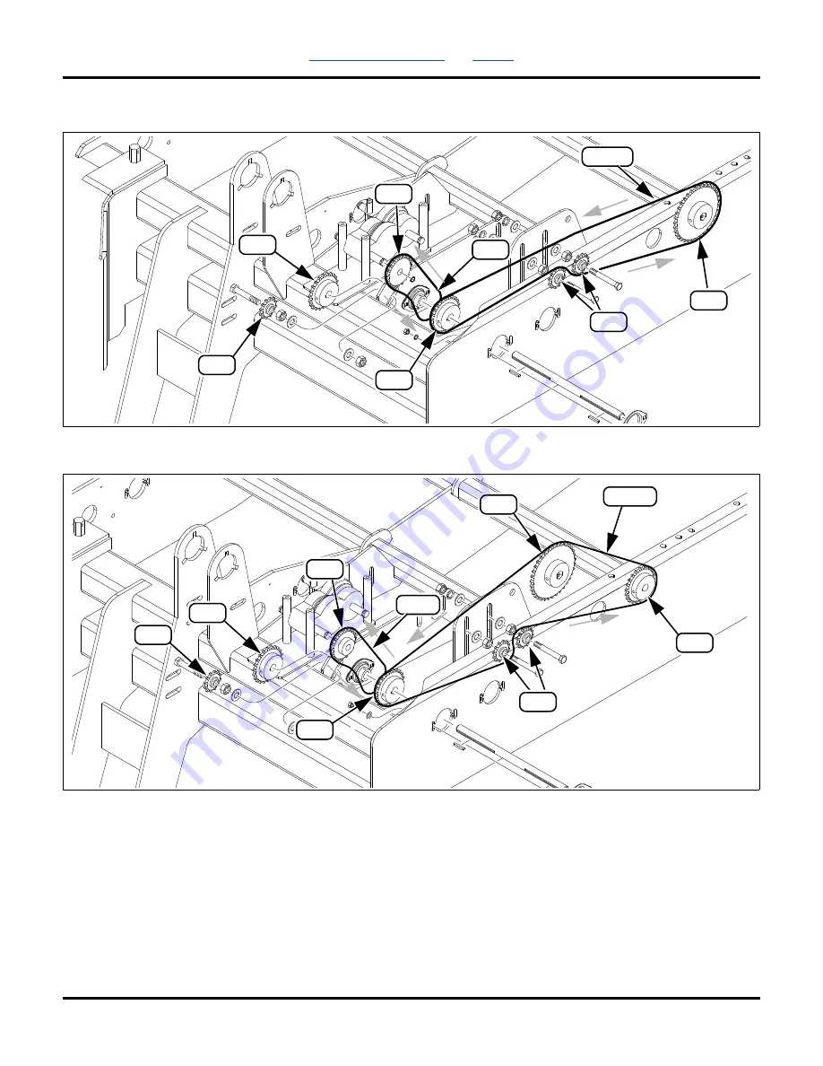
Main Seed Box Agitator (Option)

No fertilizer or small seeds is installed.

Agitator and Fertilizer Drive

No small seeds is installed.

22T

112P

28301

12i

12T

17T

40P

35T

12i

140P

28331

28T

35T

17T

12T

22T

12i

12i

40P

Summary of Contents for 3P1006NT-1575

Page 1: ...and warnings are serious follow without exception Your life and the lives of others depend on it Illustrations may show optional equipment not supplied with standard unit Table of Contents Index Original Instructions 151 144U Great Plains OPERATOR MANUAL MODELS 3P1006NT 1575 NO TILL DRILL ...

Page 2: ...tions that were originally ordered the weights and measurements are no longer accurate for your machine Update the record by adding the machine weight and measurements with the option s weight and measurements Dealer Contact Information Model Number Serial Number Machine Height Machine Length Machine Width Machine Weight Year of Construction Delivery Date First Operation Accessories Name Street Ci...

Page 3: ...g the machine It will familiarize you with safety operation adjustments and maintenance of your new equipment This manual must always be kept with your machine Great Plains wants you to be satisfied with your product If for any reason you do not understand any part of this manual or are otherwise dissatisfied please take the following actions first 1 Discuss the matter with your dealership service...

Page 4: ...nclude Air Pro Clear Shot Discovator Great Plains Land Pride MeterCone Nutri Pro Seed Lok Solid Stand Terra Guard Turbo Chisel Turbo Chopper Turbo Max Turbo Trill Ultra Till Whirlfilter and Yield Pro Brand and produce names that appear and are owner by others are trademarks of their respective owners For permission requests write to the publisher at the address below Great Plains Mfg 1525 E North ...

Page 5: ...ter 17 Loading Material 18 Loading Main and Dual Seed Boxes 18 Loading Native Grass Box 18 Loading Small Seeds Box 18 Loading Fertilizer 18 Material Rates Overview 18 Field Operation 19 Transport 19 Semi Mounted 3 Point Transport 19 Trailer Transport 20 Parking 20 Wheel Chocks 20 Storage 20 Coulter Adjustments 21 Coulter Depth All Rows 21 Coulter Depth Individual Rows 22 Coulter Down Pressure 22 C...

Page 6: ... 53 Torque Chart 54 Options 55 Agitator for Main Seed Box 55 Press Wheel Selection 55 Coulter Blades 55 Feed Cup Plug 55 Hitch Extension Kit 56 Second Ladder 56 Seed Firmers 56 Seed Lubricants 56 Carbide Disk Scraper 56 Scraper Installation 56 Weight Kit 57 Weight Bracket Installation 57 Dual Seed 58 Fertilizer 58 Series II Native Grass 58 Small Seeds 58 Small Seeds Partition 59 Small Seeds Seed T...

Page 7: ...e or in any way other than what is described in this manual machine decals or any other information provided with the machine These materials define the intended use of the machine Unauthorized modifications to the machine will relieve the manufacturer of all liability for any resulting injury or damage CE Identification The CE identification is located on the right hand side of the left gauge whe...

Page 8: ...Safety at Work Untrained or unauthorized persons are not permitted to use the machine You are responsible for ensuring that the machine is operated and maintained safely Make sure that you and all other persons that operate maintain or work in close proximity with the machine are familiar with the operating and maintenance regulations as well as the corresponding safety instructions in this operat...

Page 9: ...cal parts for wear before using machine 7 Never wear loose or bulky clothing around machine Use additional safety equipment such as hard hats eye and ear protection safety boots etc as needed 8 Do not modify the machine Unauthorized modification can result in unsafe conditions that lead to machine damage or personal injury Operation 1 Always stop the tractor put in Park and turn off engine before ...

Page 10: ...Work in a clean dry area 3 Lower the implement Put tractor in Park turn off engine To prevent unauthorized starting remove key before performing maintenance or service work 4 If work must be performed with wings raised set the wing tilt locks to the road position 5 Make sure all moving parts have stopped and all system pressure is relieved 6 Relieve hydraulic pressure before disconnecting hydrauli...

Page 11: ...railer sudden braking can cause a trailer to swerve and upset Reduce speed if trailer is not equipped with brakes Safety Chain 1 Use a chain with a strength rating equal to or greater than the gross weight of towed machinery 2 Replace chain if any links or end fittings are broken stretched or damaged 3 Do not use safety chain for towing Safety Lights and Devices 1 Always use safety lighting Slow m...

Page 12: ...from your Great Plains dealer Refer to this section for proper decal placement When ordering new parts or components also request corresponding safety decals To install new decals Clean the area on which the decal is to be placed Peel backing from decal Press firmly on surface being careful not to cause air bubbles under decal Reflectors Red Triangle 833 399C Two red triangles at rear of drill Ref...

Page 13: ... on or use tires as a step Always use ladder provided Four decals one on each side of caster wheels Entanglement Hazard 848 509C Keep hands away from moving parts when machine is in use Two decals at front of drill near gearboxes Two decals one under the cover plates on each end of dual seed box Two decals one under the cover plates on each end of native grass box 838 369C 68985 68985B 68985A 3276...

Page 14: ...ng with hydraulic system Carefully read all instructions for machine use Do not ride on the hitch when tractor is moving to avoid risk of falling One decal on 3 point hitch lower arms Crushing Hazard 848 513C Stay clear of moving parts to avoid injury Do not stand between tractor and drill while tractor is moving Two decals on 3 point hitch lower arms Two decals on lift assist axle frame Dual seed...

Page 15: ...cals can cause serious burns lung damage and even death Do not use the small seeds option to meter chemicals Use only seed in this option One decal under lid of small seeds box Crushing Hazard 848 524C Install transport locks before performing maintenance adjusting the drill or transporting Two decals one on each side of lift assist mount Falling Hazard 848 527C Always use handrail when climbing l...

Page 16: ...tires if grade is undetermined One decal on wheel chock mount Tire Pressure 848 497C Inflate tires no more than maximum pressure Two decals one on each lift assist tire rim Tire Pressure 858 668C Inflate tires no more than maximum pressure Two decals one on each drive wheel Caster Locks 848 339C Use caster locks only when loading and unloading on trailer Unlock caster locks for field use Two decal...

Page 17: ...ke before installing hitch pins This drill is a semi mounted 3 point category II hitch implement Hitch Extension Falling Object Hazard There is no top link on the drill to prevent the extension hitch from tipping forward with risk of serious injury or backward causing machine damage Never mount an extension hitch by itself on the drill If no hitch extension is required skip to step 1 On tractors w...

Page 18: ... the lift hose to the extend port of the tractor remote Connect the return hose to the retract port If lift is uneven when the hydraulic system is first charged and if air is allowed in the system bleed the system See Bleed Hydraulics starting on page 30 Great Plains hydraulic hoses are color coded to help you hookup hoses to your tractor outlets Hoses that go to the same remote valve are marked w...

Page 19: ...control spacers from the storage rod 2 and install on the cylinder rod 3 There is no factory recommendation for this as it depends on the tractor used 2 Lower the drill until the cylinders rest on the stroke control spacers 3 Pull the drill forward to put coulters and openers in the ground Make sure that lift assist casters are in trailing position Set the tractor brakes 4 When the correct level h...

Page 20: ...For hitched machines the supporting load in kg E Total weight of the machine in the front attachment in kg F Distance between the machine s center of gravity in the front attachment and front axle midpoint in m G Distance between the lower link ball midpoint and the machine s center of gravity in the rear attachment in m With hitched machine Maximum empty main seed box dual seed or native grass an...

Page 21: ... single front wheel The rear tire load bearing capacity for two wheels is equal to twice the permissible tire load bearing capacity of a single rear wheel Summary The actual values for the rear axle load must be less than the permissible values given in the tractor s operator manual The tire load bearing capacity must be greater than the values for the rear axle load given in the operator manual T...

Page 22: ...king properly and free from foreign material Make sure drive coupler is in place before operating the drill Check that the caster pivots are unlocked Drill Raise and Lower Raising and lowering the drill depends on the tractor 3 point lift arms in front and hydraulic lift assist at the rear When setup for field use the hitch and lift circuits may be operated in any order or at the same time Both mu...

Page 23: ...ist 2 Pull or back the drill onto the trailer bed On extremely narrow trailer beds it may be necessary to lock the casters before moving the drill onto the trailer Make sure the drill is aligned before moving as maneuverability is greatly reduced with lock pins in place 3 On both casters lift and turn caster lock pin handle 1 90 degrees Move in reverse lock pins snap into place in the caster plate...

Page 24: ...e the lid 3 Load seed evenly into compartments 4 To reduce wear remove shaft drive chains for main seed boxes Loading Fertilizer Fully loaded with dense fertilizer the drill can weigh an additional 318 kg or more Include this weight when checking tractor capability Load fertilizer after transport if possible If not possible set the meters to 0 and disengage the drive system to avoid fertilizer spi...

Page 25: ...heels lose contact Transport Excessive Speed Hazard Towing the drill at high speeds or with a vehicle that is too light can lead to loss of vehicle control and a serious road accident To avoid serious injury or death do not exceed the maximum speed limit of 25 kph Machine Damage Risk Always disengage caster locks before towing the drill with a tractor Tractor towing with caster wheels locked is li...

Page 26: ... Disengage caster locks 7 Unless arriving at planting ground install lift assist cylinder channel locks Parking Perform the following steps when parking the drill for 36 hours or less Refer to Storage to prepare for longer term storage 1 Position the drill on a level solid area 2 Lower the tractor 3 point lift arms and retract the lift assist cylinder until drill is on the ground 3 Set the lift as...

Page 27: ...the tilled shaft into a V shaped furrow The openers cannot generally run deeper than the coulters Running the openers too close to coulter depth may result in uneven seed depth To set the drill seeding depth 1 Set the coulter depth by raising or lowering the front drive wheel 2 Check the front to back drill level and adjust the lift assist stroke control spacers as needed 3 Set the opener depth wi...

Page 28: ...the tool bar to the bottom of the spring bar For reference the factory setting is approximately 31 8 mm 4 Determine the new bar length required and loosen the clamp bolts 1 5 Using a rubber mallet tap the spring bar 3 up or down to reach the desired level 6 Tighten the clamp bolts 7 Lower the drill and pull forward 10 m 30 feet 8 Check the coulter blade to opener blade furrow centerline alignment ...

Page 29: ... install transport locks 2 Determine the new spring length 1 desired See the table below 3 Measure the current length of the spring s to be changed If already shorter than 24 7 cm or longer than 26 cm do not further adjust them 4 Loosen the jam nut 2 5 Rotate the adjuster nut 3 until the spring is at the new length Tighten the jam nut 06 Series Row Unit Disk blades 1 2 per row unit Double disk bla...

Page 30: ... coulter height adjustments would be needed If blades are replaced spacers must be reset The ideal spacing causes the blades to be in contact for about 2 5 cm If you insert two pieces of paper between the blades the gap between them should be 1 3 mm to 44 mm A If the contact area is significantly larger or smaller or there is no contact at all adjust by moving one or more spacer washers If the con...

Page 31: ... freely scrapers are mounted between the disks to clean as the disks rotate As field conditions vary scrapers may need to be adjusted In damp conditions scrapers may need to be lowered If openers are not turning freely scrapers may need to be raised To adjust a scraper loosen the 3 8 inch bolt 1 and move the scraper as needed The standard scraper is shown below Optional spring loaded carbide scrap...

Page 32: ... some wet and sticky conditions the wheels may accumulate soil To avoid these problems you can lock up the wheels To lock up 1 Pull the catch wire aside 1 2 Pull the firming wheel arm 2 up and release the wire to catch the arm The illustration shows the opener disks remove for clarity This task can be done with disks mounted It is not necessary to remove the opener disks Drill Weight Adjustment In...

Page 33: ...ating during transport turns or in field use adjust the pressure plate bolt 2 The factory setting is 4 4 cm A from the face of the bolt head to the top of the weldment This measurement is a starting point and will need to be fine tuned from field to field as conditions vary Depending on conditions adjustment may be needed to go from field to road transport If caster brake components are ever repla...

Page 34: ... Replace any worn damaged or illegible safety decals See Safety Decals starting on page 6 Materials Clean Out Possible Dust and Chemical Fume Hazard Clean out can create dust and fumes from seed residue and seed treatment Wear a respirator and any other protective equipment specified by the seed and or seed treatment supplier Main Box and Dual Box 1 Set the seed rate handle to zero This moves the ...

Page 35: ... Wash inside of the fertilizer box with high pressure water Let the box dry before closing clean out doors Disk Maintenance Sharp Object Hazard Coulter and disk blades are sharp To avoid serious injury wear gloves when working in this area Coulter and opener disk blades wear in normal service becoming smaller in diameter Periodically check blade diameter and replace when below the recommended limi...

Page 36: ... arms Raise the drill and support the rear tool bar on jack stands 3 Loosen the jam nut 2 4 Rotate the adjuster nut 3 by the height change required Moving the eyebolt lower increases height Moving the eyebolt higher decreases height 5 Tighten the jam nut 6 Lower the drill and check the setting Bleed Hydraulics High Pressure Fluid Hazard Escaping fluid under pressure can have sufficient pressure to...

Page 37: ...ars and around the shaft bearings using at least 7 ounces of gear lube part number 788067B Keep moisture and dirt out of the gearbox Inspect the rubber seals on the gearbox drive and shifter shafts Replace if needed Spread a small skim coat of anaerobic sealant Loctite 525 or equivalent to gear case mating surfaces before bolting them back together Gearbox Damage Risk Use sealant sparingly Excess ...

Page 38: ...small seeds is also installed access the fertilizer grease fittings from below Small Seeds Shaft Bearings Coulter Hub Bearings Grease fifteen grease fittings Oil Lubrication Lubricate thoroughly with oil at the hourly intervals indicated in the arrow Fertilizer Felt Seals Apply oil to two seals If small seeds is also installed access the fertilizer seals from below 10 71001 32061 10 16381 10 i 180...

Page 39: ... empty move the seed rate adjustment handle back and forth to get oil into the square bore Grease Bearings Repack the bearings at the intervals indicated in the arrow Ground Drive Wheel Bearings Repack four ground drive wheel bearings Caster Wheel Bearings Repack two caster wheel bearings 12126 50 28299A Seasonal 32531A Seasonal ...

Page 40: ...llouts show sprocket and idler tooth counts P callouts show chain pitch count i callouts show idlers Standard Ground Drive to Gearbox This drives the main seed box through the left hand gearbox and if installed the optional main box agitator fertilizer and or small seeds 23T 12i 12i 12i 41T 12i 12i 19T 58P 188P 19T 28279A ...

Page 41: ...3P1006NT Table of Contents Index Maintenance Great Plains 151 144U 2019 03 14 35 Main Seed Box Meter Drive Main box meters are the only meters driven by the left hand gearbox 28385 89P 12i 12T 15T 12i ...

Page 42: ...ts Index Maintenance Native Grass Ground Drive Native grass is driven from the right hand ground drive One sprocket from the storage tower is mounted at the native grass meter shaft 28368A 12i 12i 12i 12i 58P 188P 19T 41T 20T 22T 21T 19T 18T 23T 16T 15T 14T 23T ...

Page 43: ...driven by the right hand gearbox A Native grass driven sprocket 14T through 23T from storage tower ships with 17T B Native grass gearbox output sprocket standard drill 19T with rate reduction kit 12T C Native grass jackshaft input sprocket standard drill 17T with rate reduction kit 22T 170P 35T 28298 17i 12i A 17T 12i 42P B C 12i ...

Page 44: ...Table of Contents Index Maintenance Main Seed Box Agitator Option No fertilizer or small seeds is installed Agitator and Fertilizer Drive No small seeds is installed 22T 112P 28301 12i 12T 17T 40P 35T 12i 140P 28331 28T 35T 17T 12T 22T 12i 12i 40P ...

Page 45: ...Plains 151 144U 2019 03 14 39 Agitator and Small Seeds Drive No fertilizer or native grass is installed With native grass installed No fertilizer is installed 135P 28332 28T 17i 17T 12T 22T 12i 35T 12i 40P 214P 28327 28T 35T 17i 17T 12T 22T 12i 42P 12i ...

Page 46: ...151 144U 2019 03 14 40 3P1006NT Table of Contents Index Maintenance Fertilizer Drive No main seed box agitator is installed Fertilizer Box Drive 135P 28302A 28T 40P 17T 12T 22T 12i 12i 140P 28345 28T 56P 12T 12i 30T ...

Page 47: ... Contents Index Maintenance Great Plains 151 144U 2019 03 14 41 Fertilizer Box Drive w Small Seeds Small Seeds Drive 79P 28346 17T 138P 42P 28T 17i 17T 12T 12i 22T 12T 12i 56P 140P 28333 28T 40P 17i 17T 12T 12i 22T 12i ...

Page 48: ...s Index Maintenance Small Seeds Drive w Native Grass No fertilizer is installed Small Seeds Box Drive D 140P if small seeds only is installed 214P if native grass and small seeds are installed 28342 28T 214P 42P 17i 17T 22T 12i 12i 12T 60P 28345 28T D 27T 17T 12i ...

Page 49: ...ents Index Maintenance Great Plains 151 144U 2019 03 14 43 Small Seeds Box Drive w Fertilizer When fertilizer is also installed small seeds jackshaft is driven from fertilizer jackshaft 79P 13742 17T 60P 12i 12i 17T 17T 27T ...

Page 50: ...Great Plains 151 144U 2019 03 14 44 3P1006NT Table of Contents Index Maintenance Dual Seed Ground Drive Dual seed is driven from the right hand ground drive 12i 12i 12i 12i 58P 188P 19T 41T 23T 28368B ...

Page 51: ...44U 2019 03 14 45 Dual Seed Meter Drive Dual box meters are driven by the right hand gearbox Dual Seed and Small Seeds Drive Dual box meters are driven by the right hand gearbox 19T 25T 19T 17i 35T 42P 31627A 176P 20T 12i 31628 28T 214P 17i 17T 12T 22T 12i 12i 42P ...

Page 52: ...Great Plains 151 144U 2019 03 14 46 3P1006NT Table of Contents Index Maintenance Electrical Diagram 1 P clip 2 Wire tie 71213 1 1 2 2 2 2 2 2 2 2 ...

Page 53: ...3P1006NT Table of Contents Index Maintenance Great Plains 151 144U 2019 03 14 47 Hydraulic Diagram 1 P clip 2 Wire tie 71218 1 1 2 2 ...

Page 54: ...Great Plains 151 144U 2019 03 14 48 3P1006NT Table of Contents Index Maintenance Lift Assist Hydraulic Connections 38205A ...

Page 55: ...ud build up on disk scraper Adjust disk scraper page 25 Disk scraper adjusted too tight restricting movement Adjust disk scraper page 25 Failed disk bearings Replace disk bearings Bent or twisted opener frame Replace opener frame Planting conditions too wet Wait until drier weather Too much opener down pressure If opener disks turn freely by hand but not in the field reduce down pressure page 25 I...

Page 56: ... scraper Feed cup sprockets locked up or twisted feed cup drive shaft Foreign matter lodged in one or more feed cup sprockets Clean out feed cup sprockets Use clean seed Dried liquid insecticide inside feed cups Remove build up by disassembling each feed cup and scraping foreign substance from turn surfaces Coulters not going deep enough Not enough down pressure Adjust coulters when a few rows are...

Page 57: ...ier conditions Passes misaligned Check that planting passes are not leaving gaps or causing overlap Wheel slippage If consistent develop a correction factor for your conditions Check that acremeter is for your drill Activate display Lower left corner must be 1405 3 revs ha Contact dealer if otherwise Acremeter battery failing Replace acremeter Unit is sealed and battery is not replaceable Problem ...

Page 58: ...ve Wheels 5 70 8 8 Ply 4 bolt rim Dimensions Height 2 4 m Transport Height Varies by Tractor Transport Width 3 m Transport Length 3 8 m w lift assist Transport Clearance 40 6 cma and depends on tractor hitch a With rear lift lock channels installed and semi mounted hitch elevated to drill level Lower Linkage Height 59 cm Capacities Main Seed Box 705 liters Dual Seed Box 352 liters Native Grass Box...

Page 59: ... and SGS Drill with NG and SGS All Boxes Empty 2187 kg 2334 kg 2317 kg 2214 kg 2368 kg 2454 kg Main Box Full and Fertilizer Full if installed 2767 kg 3227 kg 2898 kg 2794 kg 3261 kg 3035 kg All Boxes Empty with Weights 2717 kg 2863 kg 2847 kg 2744 kg 2898 kg 2984 kg Main Box Full Weights Fertilizer Full if installed 3297 kg 3757 kg 3428 kg 3324 kg 3791 kg 3565 kg Tire Size Tire Pressure Wheel Bolt...

Page 60: ... 525 830 1150 1 12 370 955 1350 M30 X 3 5 960 1510 2100 11 8 7 480 1080 1750 M30 X 2 1060 1680 2320 11 8 12 540 1210 1960 M36 X 3 5 1730 2650 3660 11 4 7 680 1520 2460 M36 X 2 1880 2960 4100 11 4 12 750 1680 2730 13 8 6 890 1990 3230 a in tpi nominal thread diameter in inches threads per inch 13 8 12 1010 2270 3680 b N m newton meters 11 2 6 1180 2640 4290 11 2 12 1330 2970 4820 c mm x pitch nomin...

Page 61: ... choice of press wheels Additional wheels are available and all may be field installed This manual does not list kit part numbers as the available wheels are region specific Consult your dealer Coulter Blades The standard coulter blades on the 3P1006NT drill are 43 2 cm 820 156C turbo or 820 018C fluted Available replacement and alternate blades include Feed Cup Plug The feed cup plug stops seed f...

Page 62: ...nts Use seed lubricants only in native grass planting Carbide Disk Scraper Carbide disk scrapers are spring loaded and require no adjustment Disk scrapers are compatible with the standard seed flap and Seed Lok Order one per row Scraper Installation Start with row 1 left most row unit 1 Remove one or both disk blades for access to the mount 1 Note the position of bushings and spacers for correct r...

Page 63: ...kg suitcase style tractor weights The weight brackets are available as a separate kit Kits do not include weights Weight Bracket Installation 1 Position one of the weight brackets 1 at the left end of the top front frame Position the beveled edges and weight mount 2 to the back 2 Install the u bolts 3 3 Install the decal mount 4 on the u bolts 4 Secure the weight bracket to the frame with lock was...

Page 64: ...el meters and delivery tubes The fertilizer attachment is compatible with a small seeds option The fertilizer attachment is not compatible with the native grass Ask your dealer for ordering information Series II Native Grass The native grass option is designed to seed fluffy hard to plant grasses Standard equipment includes dedicated ground drive and gearbox system acremeter 352 liter box with Ser...

Page 65: ...e up when drilling across slopes and in other situations where the seed is particularly fluid Partitions sold individually Order the quantity desired Small Seeds Seed Tube Plug The small seeds cup plug stops seed flow from the small seeds box above the meter Order one per row Description Part Number RMVBL SMALL SEED BOX PARTITION 123 409D Description Part Number SML SDS CUP PLUG 133 315H 17028 274...

Page 66: ...that after unloading there is room enough to connect a tractor to the drill Have all major components fasteners and pins that were shipped with the drill Have a copy of the parts manual on hand If unsure of proper placement or use of any part or fastener refer to the parts manual Tools required a properly rated forklift or two forklifts with the properly rated combined capacity for the drill hoist...

Page 67: ... the assembly area Machine Damage Risk Lift the drill by the chains only Do not wrap chains around the seed cups or seed cup channels Make sure the front chains are positioned at each end of the front frame tube and rear chains through holes in the end plates 8 Making sure to keep the drill level front to back and side to side slowly lower the drill to the ground 9 Lower the forks remove the chain...

Page 68: ...the caster assembly to align with the parallel arms 3 From the left hand side slide the pivot tubes 8 into the pivot mount 9 and through the outer pivot tube at the rear of the arms Make sure the pivot tubes are pushed in as far as possible 4 Insert the 1 x 18 inch bolts 10 from the right hand side of the pivot mount Secure the bolts with flat washers 11 lock washers 12 and nuts 13 5 If necessary ...

Page 69: ...he adapter 4 to port 2 of the valve 5 Install the 9 16 MJIC 9 16 MORB elbow to the rod end of the hydraulic cylinder 6 Secure the short hydraulic hose 5 to the bottom of the tee and the elbow at the rod end of the cylinder 7 Secure one of the long hydraulic hoses 6 to the top of the tee 8 Install the other long hydraulic hose 7 to the adapter 9 Route the long hoses to the front of the drill 10 Pla...

Page 70: ...to the bottom front frame tube on the end of the frame Secure with two u bolts 11 lock washers 12 and nuts 13 4 Attach the fluorescent panel 14 to the sign mount assembly with four 3 8 x 3 4 inch bolts 15 and nylock nuts 16 5 Repeat the above steps for the other front panel and LED light Install Rear Left Hand Panel and Lights 1 Mount the left hand rear sign mount 1 to the lift assist arm near the...

Page 71: ...Lights 1 Mount the right hand rear sign mount 1 to the lift assist arm near the right caster wheel Secure with two u bolts 2 lock washers 3 and nuts 4 2 Install the speed limit sign 5 to the rear mount with two 10 bolts 6 flat washers 7 lock washers 8 and nuts 9 3 Install the sign mount bracket 10 onto the right hand mount approximately 12 cm from the end Secure with a u bolt 11 lock washers 12 an...

Page 72: ... of Contents Index Assembly Install Wiring Harness 1 Install the wiring harness Route the wires with the two female two pin connectors 1 to the front LED lights 2 2 Route the remaining wires with male connectors to the rear of the drill 1 2 2 1 71028A ...

Page 73: ...ie to connect the wiring harness to the mounting post 8 for the SMV 6 On the left hand side route the short wire with two pin connector 9 to the license plate light 7 On both sides route the wires with the three pin connectors 10 to the red lights Route the wires with the two pin connectors 11 to the amber lights 8 Secure the wiring harness with cable ties Wire Damage Risk Make sure all harnesses ...

Page 74: ...is used for dual seed fertilizer or native grass if installed The rear hole is used for small seeds if installed Some components in the following instructions may already be installed Use the illustrations and instructions as a reference Begin on the left hand side of the drill and repeat the steps for each row Main Seed Hose 1 Place the 1 5 8 inch hose clamp 1 onto the inlet end of the seed hose ...

Page 75: ...utlet end of the hose up against the ribs Slide the outlet end of the hose fully onto the fertilizer tube inlet Move the clamp until it is about 1 2 inch from the reinforcement ring 5 Repeat the above steps for each opener Native Grass Hose 1 Insert the native grass tube 1 into the middle hole 2 in the opener frame Secure with two 10 x 3 4 inch screws 3 and flat washers 4 2 Place a band clamp 5 on...

Page 76: ...e small seeds hose onto the small seeds tube Slide the hose clamp to about 1 2 inch from the end of the hose 5 Repeat the above steps for each opener Pre Delivery Checklist After assembling the drill and before delivery Check that all working parts are moving freely bolts are tight and cotter pins are spread Check for proper tension and alignment on all drive chains Check that all safety decals an...

Page 77: ...p Gottmadingen N V and Industriepark 312 authorized for D 78244 Gottmadingen compile the technical file Germany established in EC Declare under our sole responsibility that the product Designation of machine Seed drill Machine type Box Drill 3P1006NT Valid from serial no GP A 1302W corresponds to the above mentioned directive The following harmonized standards are applied EN ISO 4254 1 2015 Salina...

Page 78: ...G gearbox 31 grease fittings 31 H headphones 4 hitch extension 11 56 hitching 11 hydraulic diagram 47 hydraulics bleeding 30 fluid 5 hookup 12 hose color code 12 setup 63 L leveling 12 lift assist adjustment 30 casters 17 cylinder 16 17 eyebolts 30 installation 61 lights 5 64 loading material 18 lock channel 16 lowering 17 M machine identification 1 main seed box agitator 55 maintenance safety 4 N...

Page 79: ...Table of Contents Index ...

Page 80: ...Great Plains Mfg 1525 E North St P O Box 5060 Salina KS 67402 ...

Reviews: