


7 - 39
1. When disconnecting hoses, have an open top
container to drain hydraulic oil into.
2. Clean all fittings and hoses where maintenance is
to be performed, prior to removing hoses to avoid
hydraulic system contamination. Cap hoses,
fittings and hydraulic component ports.
3. Repair or replace any worn or damaged hydraulic
items.
4. Fittings which use an O-ring seal do not use a
hydraulic sealer for preventing leaks. Fittings
without an O-ring seal, should use a hydraulic
sealer. Use caution not to get hydraulic sealer into
hydraulic system.
5. After any hydraulic hose maintenance, prime the
hydraulic system.
7.4 STEERING BOX REMOVAL
1. Remove the front control panel. It is not necessary
to disconnect the head light to remove the front
panel.
2. Remove the steering wheel and steering column
boot.
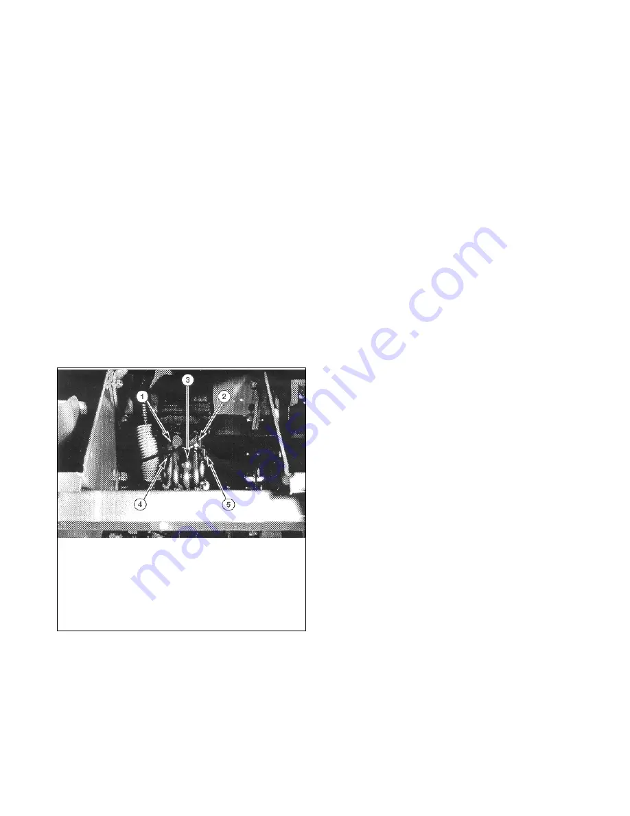
3. Disconnect the five hydraulic hoses at the power
steering unit and cap. See Figure 52.
.
NOTE: It may be necessary to remove the top nylon
bushing from the top of the control panel to avoid bend-
ing the panel.
4. Support the power steering unit and remove the
four mounting nuts and slide the power steering
unit out of the unit.
5. Repair or replace any worn or damaged parts.
7.5 STEERING BOX INSTALLATION
1. Slide the power steering unit into place and secure
with the four nuts. Install the nylon bushing if
removed.
2. Connect the five hydraulic hoses to the power
steering unit. See Figure 52.
3. Install the steering column boot. Apply anti-seize to
steering column splines and install the steering
wheel.
4. Install the front control panel. If the headlight was
disconnected, refer to the electrical schematic for
proper wiring.
5. Normal steering operations should bleed the
hydraulic system sufficiently.
7.6 STEERING CYLINDER REMOVAL
1. Disconnect the two hydraulic hoses at the steering
cylinder and cap.
2. Remove the two bolts at the two rod end
assemblies and remove the steering cylinder.
3. Repair or replace any worn or damaged parts.
7.7 STEERING CYLINDER INSTALLATION
1. Install the steering cylinder by installing the two
bolts at the rod end assemblies. Install the steering
cylinder with the ram to the left side of the unit.
2. Connect the two hydraulic hoses to the steering
cylinder.
3. Normal steering operations should bleed the
hydraulic system sufficiently.
7.8 TIE ROD ADJUSTMENT
1. Refer to Wheel Alignment for proper lengths of all
three tie rods and correct toe-in dimensions.
Figure 52
1. Steering Cylinder,
Right Side
2. Steering Cylinder, Left
Side
3. Auxiliary to Manifold
4. IN from Transmission
5. OUT to Hydraulic
Valve
Summary of Contents for 989003
Page 1: ......
Page 21: ...6 21 6 1 HYDRAULIC SCHEMATIC SECTION 6 DRIVE TRAIN Figure 16...
Page 53: ...10 53 10 11 WIRING DIAGRAMS Promaster 400 30 H...
Page 54: ...10 54 Promaster 400 22 H...
Page 64: ...12 64 Figure 62 Mower Mounting PF3170 Figure 63 Mower Gearbox...


