12
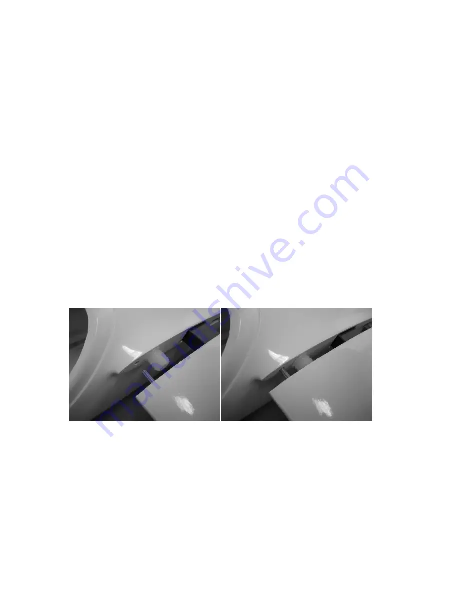
Now is a good time to install the compression strut, supplied as part of the wooden
parts kit. Carefully adjust the length of the hardwood piece to fit inside the width of
the fuselage, just aft of the trailing edge incidence pins. It is important that the strut
fit snugly, without distorting the shape of the fuselage, but correcting for any minor
manufacturing tollerence in respect of the wing/fuselage fairing. The strut is
bonded into place using suitably thickened epoxy resin.
Once satisfied with the fit and allignment of the wings on the fuselage, the wing
incidence pins may be bonded into the holes in the root ribs. The pins should
protrude about 7 – 10 mm from the wing roots. Be sure to make one pin in each wing
a little longer than the other, and round off the end of the pins to facilitate easier
assembly at the flying field. Once both wings have been marked and drilled, carefully
check the alignment before bonding the incidence pins into place. Apply a suitable
release agent to the holes in the fuselage fairing before applying a suitably thickened
epoxy. Then fit the wings to the fuselage, with the steel joiner installed to allow the
epoxy to cure overnight. Tip: Use a layer of kitchen film between the wing/fuselage
joint to avoid any excess epoxy from forming a permanent joint!
To complete the work on the wing halves glue the pressure pins (multilocks) into the
blind holes in the root ribs. In order to do this, press the pressure pins into their
counterparts in the fuselage. If necessary rework the blind-holes slightly to
accomdate the pressure pins. Apply a little adhesive in the blind-holes in the root ribs
and assemble the wing on the wing joiner and allow to cure.
TIP: Once again, use a layer of kitchen film between the wing/fuselage joint to avoid
any excess epoxy from forming a permanent joint!
Fuselage and Canopy
Fit the pin carrier strip (grooved strip) into the canopy. Then deburr the edges of the
pin and bond it securely into grooved strip. The pin should protrude about 22mm
beyond the end of the carrier strip. Glue the pin/carrier assembly such that that the
pin protrudes about 6 mm beyond the edge of the canopy and a distance of about 3
mm remains, measured on the inside of the canopy. Carefully file (not too much!)
with a round file a small groove into the fuselage in the centre of the front canopy
section, into which the canopy pin will lock. The canopy retainer consists of the GRP-
spring. The spring protrudes 10 mm beyond the rear canopy rim. The canopy spring
is fixed with superglue and subsequently laminated over with 1-2 layers of glass-


