background image

Chapter 1 Introduction   

1-10

Profile Video File Server Installation


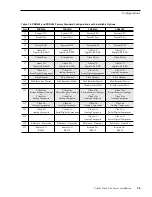
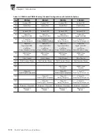
Table 1-3. PDR304 and PDR308 Factory Standard Configurations with Installable Options

Slot

PDR304A

PDR304D

PDR308A

PDR308D

J1

System CPU

System CPU

System CPU

System CPU

J2

Parallel Port

Parallel Port

Parallel Port

Parallel Port

J3

J4

System SCSI

System SCSI

System SCSI

System SCSI

J5

Audio I/O

Digital AES/EBU

Audio I/O

Digital AES/EBU

Audio I/O

Digital AES/EBU

Audio I/O

Digital AES/EBU

J6

Video Out

Analog Composite

Video Out

Picture Monitor (Analog)

Video Out

Analog Composite

Video I/O

Serial Digital Component

J7

Audio I/O

Digital AES/EBU

or

Video Out

Picture Monitor (Analog)

Audio I/O

Digital AES/EBU

or

Video Out

Picture Monitor (Analog)

Audio I/O

Digital AES/EBU

or

Video Out

Picture Monitor (Analog)

Audio I/O

Digital AES/EBU

or

Video Out

Picture Monitor (Analog)

J8

MPEG Video

Decoder

MPEG Video

Decoder

MPEG Video

Decoder

MPEG Video

Decoder

J9

Fibre Channel

Fibre Channel

Fibre Channel

Fibre Channel

J10

Disk Recorder Master

Disk Recorder Master

Disk Recorder Master

Disk Recorder Master

J11

J12

MPEG Video

Decoder

MPEG Video

Decoder

J13

Video I/O

Serial Digital Component

Video I/O

Serial Digital Component

Video I/O

Serial Digital Component

J14

Video I/O

Serial Digital Component

Video I/O

Analog Composite

Video I/O

Serial Digital Component

J15

Video I/O

Serial Digital Component

Video I/O

Analog Composite

Video I/O

Serial Digital Component

J16

Reference / Timecode

Reference / Timecode

Reference / Timecode

Reference / Timecode

J17

Remote I/O

RS422

Remote I/O

RS422

Remote I/O

RS422

Remote I/O

RS422

Summary of Contents for PDR 400

Page 1: ...P D R 2 0 0 P D R 3 0 0 P D R 4 0 0 Installation Manual 071 8005 00 MARCH 23 2000 PROFILE FAMILY V I D E O F I L E S E R V E R S ...

Page 2: ... or disclosure by the United States Government is subject to restrictions as set forth in subparagraph c 1 ii of the Rights in Technical Data and Computer Software clause at DFARS 252 277 7013 or in subparagraph c 1 and 2 of the Commercial Computer Software Restricted Rights clause at FAR 52 227 19 as applicable Manufacturer is Grass Valley Group Inc P O Box 59900 Nevada City California 95959 7900...

Page 3: ...de 24 hour Emergency Hotline 530 478 4148 Contract and warranty customers World Wide Web http www grassvalleygroup com support FTP Site ftp grassvalleygroup com Users Group profile users grassvalleygroup com France 01 69 86 83 47 United Kingdom 01628 405830 Germany 0221 9477 446 Other 44 1628 405840 Italy 02 25086606 Australia from overseas 02 9888 0100 61 2 9888 0100 Japan 81 3 3448 3111 Korea 82...

Page 4: ...Grass Valley Group Product Support iv Profile Video File Server Installation ...

Page 5: ...nel Connections 2 7 Connecting the Mouse and Keyboard 2 8 Connecting the Monitor 2 8 Connecting the Reference Genlock 2 9 Connecting Video 2 10 Connecting Serial Digital Video 2 10 Connecting Analog Composite Video I O 2 11 Connecting Analog Composite Monitor 2 12 Connecting Analog Composite Video Out 2 13 Connecting Component Analog Video 2 14 Connecting Audio 2 15 Connecting 16 Channels AES EBU ...

Page 6: ...ile Systems 4 2 Cascading Several Hubs 4 2 Point to Point Network Connection 4 3 Connecting Ethernet 4 4 Ethernet Interface Configuration 4 4 Configuring Ethernet for TCP IP 4 5 Testing Your Ethernet Connection 4 5 Connecting Fibre Channel 4 6 Appendix A Specifications General Information A 1 Test Equipment A 1 Electrical Specifications A 2 Environmental Criteria A 10 Mechanical Specifications A 1...

Page 7: ...ections for 16 Analog and 16 Digital Audio Channels 2 23 2 19 ASPB Connections for 32 Analog and 32 Digital Audio Channels 2 25 2 20 SCSI Cable Connections 2 26 2 21 Example 1 Connecting a PDX218 Disk Expansion Chassis 2 27 2 22 Example 2 Connecting two PDX218 Disk Expansion Chassis 2 28 2 23 Example 3 Profile Video File Server to PLS 200 Connections 2 29 2 24 Example 4 Profile Video File Server t...

Page 8: ...erver Storage Capacity Estimates 1 16 2 1 Audio Interface Chassis Summary 2 15 2 2 RS 422 Interface Board Connector 2 32 2 3 Power Cords for the Profile Video File Server and PAC 208 2 35 3 1 Rear Panel Board Indicators 3 8 A 1 Serial Digital Video Input Output A 2 A 2 Analog Composite Video Output A 3 A 3 Analog Composite Video I O A 4 A 4 Component Analog Video Input A 5 A 5 Component Analog Vid...

Page 9: ...output terminals of the product ensure that the product is properly grounded Do Not Operate Without Covers To avoid electric shock or fire hazard do not operate this product with covers or panels removed Do Not operate in Wet Damp Conditions To avoid electric shock do not operate this product in wet or damp conditions Do Not Operate in an Explosive Atmosphere To avoid injury or fire hazard do not ...

Page 10: ...the marking CAUTION indicates a hazard to property including the product Symbols on the Product The following symbols may appear on the product DANGER high voltage Protective ground earth terminal ATTENTION refer to manual Service Safety Summary Do Not Service Alone Do not perform internal service or adjustment of this product unless another person capable of rendering first aid and resuscitation ...

Page 11: ...ssions from digital apparatus set out in the Radio Interference Regulations of the Canadian Department of Communications Le présent appareil numérique n émet pas de bruits radioélectriques dépassant les limites applicables aux appareils numériques de la classe A préscrites dans le Règlement sur le brouillage radioélectrique édicté par le ministère des Communications du Canada Canadian Certified AC...

Page 12: ...re at a distance of 100 mm from the source focused through a lens with a focal length of 100 mm FCC Emission Limits This device complies with Part 15 of the FCC Rules Operation is subject to the following two conditions 1 This device may not cause harmful interference and 2 this device must accept any interference received including interference that may cause undesirable operation This device has...

Page 13: ...EG Video File Server and the PDR400 DVCPRO Video File Server This Installation manual provides an overview of the Profile Video File Server shown in Figure 1 1 and descriptions of the tasks listed below Installing the video file server into an equipment rack Connecting Video and Audio I O Connecting SCSI devices Connecting Fibre Channel and Ethernet Configuring Ethernet IP Address Power On Off pro...

Page 14: ...on information Chapter 2 Mechanical Installation This chapter describes the physical installation of the system up to initial power on Chapter 3 Starting Your Profile System This chapter consists of procedures to turn system power On and Off to set up the system and to verify correct installation of the Profile Video File Server Chapter 4 Networking Your Profile System This chapter describes the E...

Page 15: ...EG encoders and decoders to the Profile Video File Server while retaining all the capabilities and optional configurations of the PDR200 Two MPEG boards one with one encoder and two decoders the other with four decoders provide many combinations of capabilities to meet your needs The JPEG codecs on the Master and Slave Enhanced Disk Recorder boards remain available as resources for record play cha...

Page 16: ...NT operating software is loaded on the dedicated system hard disk which is also used for application storage Control is via an internal Pentium based CPU board Other features include Super VGA monitor output Auto switching 10 100BASE T Ethernet network support Control interfaces RS 232 two rear panel ports RS 422 eight ports through breakout panel Keyboard and mouse Parallel port Front panel contr...

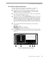
Page 17: ...activity They are mapped right to left to the physical location of each hard disk drive in the chassis and flash on when activity occurs on the associated disk A LED should flash on for every disk installed in the unit If a LED fails to flash on for each disk in the unit or if a LED remains lit there may be a problem with the one of the disks If you do not have any internal disk storage which is a...

Page 18: ...A Profile Video File Server shipment includes the following items 1 Manual Profile Family User 1 Manual Installation Profile System Software Release Notes Software Package which includes the latest version of Profile System Software and an Emergency Repair diskette Windows NT software package 1 Keyboard Grass Valley Group part number 119 4899 XX 1 Mouse Grass Valley Group part number 119 4330 XX E...

Page 19: ...face Adapter copper to fiber for fibre channel networking S VGA Monitor PAC208 216 Analog Digital Profile Audio Chassis XLR216 or BNC216 Digital Audio Breakout Panel PDX218 Disk Drive Expansion Chassis 1 SCSI Terminator 011 0166 00 Eight connector DB25 XLR breakout cable for longitudinal time code I O 6 ft Grass Valley Group part number 174 3249 XX Eight connector breakout cable with DB25 connecto...

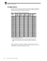
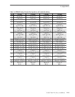
Page 20: ...G Encoders Number of MPEG Decoders Number of DVCPRO25 CODECs Video I O Type PDR202A 2 0 0 0 Analog PDR204A 4 0 0 0 Analog PDR202D 2 0 0 0 Digital PDR204D 4 0 0 0 Digital PDR304A 2 0 4 0 Analog PDR304D 2 0 4 0 Digital PDR308A 2 0 8 0 Analog PDR308D 2 0 8 0 Digital PDR312A 2a a 4 if Slave Disk Recorder is installed 1 2 0 Analog PDR312D 2a 1 2 0 Digital PDR316A 2a 1 6 0 Analog PDR316D 2a 1 6 0 Digita...

Page 21: ...Analog Composite J9 Fibre Channel Fibre Channel Fibre Channel Fibre Channel J10 Disk Recorder Master Disk Recorder Master Disk Recorder Master Disk Recorder Master J11 Disk Recorder Slave Disk Recorder Slave J12 Video Out Picture Monitor Analog or Video Out Analog Composite Video Out Picture Monitor Analog or Video Out Analog Composite Video Out Picture Monitor Analog or Video Out Analog Composite...

Page 22: ...ut Picture Monitor Analog Audio I O Digital AES EBU or Video Out Picture Monitor Analog Audio I O Digital AES EBU or Video Out Picture Monitor Analog J8 MPEG Video Decoder MPEG Video Decoder MPEG Video Decoder MPEG Video Decoder J9 Fibre Channel Fibre Channel Fibre Channel Fibre Channel J10 Disk Recorder Master Disk Recorder Master Disk Recorder Master Disk Recorder Master J11 J12 MPEG Video Decod...

Page 23: ... Analog Audio I O Digital AES EBU or Video Out Picture Monitor Analog Audio I O Digital AES EBU or Video Out Picture Monitor Analog J8 MPEG Video Encoder Decoder MPEG Video Encoder Decoder MPEG Video Encoder Decoder MPEG Video Encoder Decoder J9 Fibre Channel Fibre Channel Fibre Channel Fibre Channel J10 Disk Recorder Master Disk Recorder Master Disk Recorder Master Disk Recorder Master J11 Disk R...

Page 24: ...dio I O Digital AES EBU or Video Out Picture Monitor Analog Audio I O Digital AES EBU or Video Out Picture Monitor Analog J8 MPEG Video Encoder Decoder MPEG Video Encoder Decoder J9 Fibre Channel Fibre Channel J10 Disk Recorder Master Disk Recorder Master J11 Disk Recorder Slave Disk Recorder Slave J12 MPEG Video Encoder Decoder MPEG Video Encoder Decoder J13 Video I O Serial Digital Component J14...

Page 25: ... Picture Monitor Analog Audio I O Digital AES EBU or Video Out Picture Monitor Analog J8 Disk Recorder Slave Disk Recorder Slave Disk Recorder Slave Disk Recorder Slave J9 Fibre Channel Fibre Channel Fibre Channel Fibre Channel J10 Disk Recorder Master Disk Recorder Master Disk Recorder Master Disk Recorder Master J11 DVCPRO Four codec DVCPRO Four codec DVCPRO Four codec DVCPRO Four codec J12 DVCP...

Page 26: ...options by looking at the bottom panel just below the rear panel board connectors A configuration label which identifies the board installed in the slot above the label has been attached to assist you in making connections to your Profile system Figure 1 3 shows the location of the configuration label Figure 1 3 Configuration Labels Locations 9676 26 Labels ...

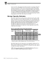
Page 27: ...Internal or PDX218 PDR202 48Mb s 48Mb s 48Mb s PDR204 not available 48Mb s 48Mb s PDR312 24Mb s 50Mb s 50Mb s PDR304 24Mb s 50Mb s 50Mb s PDR324 not available 24Mb s 24Mb s PDR 316 not available 24Mb s 24Mb s PDR308 not available 18Mb s 24Mb s Table 1 8 Maximum Video Data Rates Per Channel With PRS255 RAID Storage Chassis Profile Models with the PRS255 RAID Storage Chassis Maximum Video Data Rate ...

Page 28: ...he video data rate used to record the video signal unless you are using DVCPRO 25 compression which operates at a fixed 25Mb s data rate or DVCPRO 50 compression which operates at a fixed 50Mb s data rate For more information about setting the video data rate refer the appropriate sections of the Profile Family User Manual Video storage times are estimates within 10 and include 2 audio channels an...

Page 29: ...you want to use the DVCPRO codecs as independent codecs all of your video inputs must be auto timed to the Reference input In Configuration Manager select Enable Auto Timing for each input You must ensure that each input actually auto times by checking that the Auto Timed indicator in the Video Input dialog box is lit Refer to Using the Profile Configuration Manager in the Profile Family User Manu...

Page 30: ...Chapter 1 Introduction 1 18 Profile Video File Server Installation ...

Page 31: ...e Profile Video File Server system installs in a standard 19 inch equipment rack Rack slide tracks shipped with the Profile Video File Server and the Profile Audio Chassis allow them to slide in and out without having to remove them from the rack However if the rack does not already have rack slides installed or if the slides are not correctly positioned you will have to use those shipped with the...

Page 32: ...ting rack slides in the equipment rack bear the following in mind The Profile Video File Server occupies 5 rack units RUs The PAC208 216 occupies 2 RUs Figure 2 1 Rack Slide Set for Right Side of Profile Chassis and Rack Profile Chassis Section Automatic Rack Section 10 32 PHS 10 32 PHS Flat Nut Flat Nut Bar Intermediate Stop Latch Rear NOTE Right hand and left hand stationary section is designate...

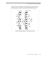
Page 33: ...oles on the rack Notice that the hole spacing can vary with the rack type When mounting the slides in racks with EIA spacing make sure that the slides are attached to the 0 5 inch spaced holes Figure 2 2 Spacing Specification for Mounting Holes in a Rack 1 250 in MIL STD 189 UNIVERSAL SPACING 0 500 in 0 625 in 1 250 in 1 250 in 0 625 in ...

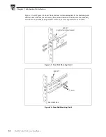
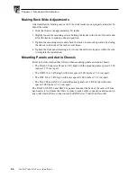
Page 34: ...ng details for both deep and shallow racks Mount the rails using the enclosed hardware Make sure the stationary sections are horizontally aligned and are level as well as parallel to each other Figure 2 3 Front Rail Mounting Detail Figure 2 4 Rear Rail Mounting Detail BAR NUT Useif thefront railis nottapped BAR NUT REAR RACK RAIL PNH ...

Page 35: ...Figure 2 5 WARNING To prevent injury two people are required to lift the Profile Video File Server It is too heavy for one person to install in the rack WARNING To prevent serious injury insure that the rack is anchored to the floor so that it cannot tip over when the Profile Video File Server is extended out of the rack 2 Insert the ends of the chassis sections into the slide out sections 3 Push ...

Page 36: ...crews once the cabinet is in place within the rack to complete the installation Mounting Panels and Audio Chassis Refer to the information that follows when mounting panels and audio chassis The RS 422 Connector Panel is 1 RU high with the mounting holes spaced 1 250 inches 3 175 cm apart The XLR216 is 2 RUs high with holes spaced 3 000 inches 7 62 cm apart The BNC216 is 1 RU high with holes space...

Page 37: ...installed As you go through these instructions simply ignore a board you do not have installed Note that any rear panel slot which does not have a board installed will have a blank cover over the rear panel slot NOTE Insure that power switches of all equipment to be installed are in the Off O positions To insure compliance with EMI standards all BNC cable connections require that an EMI suppressio...

Page 38: ...gure 2 7 Connect the mouse and keyboard as shown in Figure 2 7 Figure 2 7 Mouse Keyboard and S VGA Monitor Connections Connecting the Monitor The S VGA monitor connector is located on the System CPU board located in slot J1 Connect the S VGA Monitor cable to the 15 pin connector as shown in Figure 2 7 J1 J13 J14 J6 J7 J4 J3 J2 J5 J12 J11 J9 J8 J10 9676 68 System CPU Mouse Keyboard Monitor Parallel...

Page 39: ...des Longitudinal Time Code interfaces four in and four out See Figure 2 8 Figure 2 8 Reference Genlock Cable Connections To make cable connections to the Reference Genlock board refer to Figure 2 8 and 1 Attach the optional Longitudinal Time Code breakout cable Figure 2 9 to the 25 pin DIN connector Figure 2 9 Breakout Cable 2 Place EMI gaskets on the BNC connectors as shown in Figure 2 6 page 2 7...

Page 40: ...board Figure 2 10 shows serial digital cable connections for a typical location slot J14 Refer to the rear panel labels or Tables 1 2 through 1 6 in Chapter 1 pages 1 9 through 1 13 to determine the slot location of this board in your system 1 Place EMI gaskets on the four BNC connectors as shown in Figure 2 6 page 2 7 2 Attach two BNC cables from serial digital sources to the IN A and IN B connec...

Page 41: ...oard is also equipped with an S Video connector which allows video input to the Profile system directly from a source such as a video cassette recorder However the S Video device takes the place of one of the inputs either In A or In B The board provides time base correction for any one input If the Analog Composite Video I O board is installed refer to Figure 2 11 for an example and 1 Place an EM...

Page 42: ...ides text overlay for source identification Figure 2 12 shows composite monitor cable connections for a typical location slot J12 Refer to the rear panel labels or Tables 1 2 through 1 6 in Chapter 1 pages 1 9 through 1 13 to determine the slot location of this board in your system 1 Place an EMI gasket on each BNC connector as shown in Figure 2 6 page 2 7 2 Attach four BNC cables for composite vi...

Page 43: ...cation slot J6 Refer to the rear panel labels or Tables 1 2 through 1 6 in Chapter 1 pages 1 9 through 1 13 to determine the slot location of this board in your system 1 Place an EMI gasket on each BNC connector as shown in Figure 2 6 page 2 7 2 Attach four BNC cables for composite video outputs to the OUT A OUT B OUT C and OUT D connectors 3 Attach a BNC cable for the Out D output with time code ...

Page 44: ... labels or Tables 1 2 through 1 6 in Chapter 1 pages 1 9 through 1 13 to determine the slot location of this board in your system To make connections to the Analog Component Video In board refer to the example in Figure 2 14 and 1 Place an EMI gasket on the three BNC connectors as shown in Figure 2 6 page 2 7 2 Attach three BNC cables from an appropriate component analog video source to the connec...

Page 45: ...1 contains a summary of interface chassis available NOTE Interface chassis must be connected to both ASPBs for operation with 32 channels of analog or AES EBU digital audio To determine if the PAC200 Analog Audio Chassis is a PAC208 or PAC216 look at the identification tag toward the rear on the left side of the chassis Table 2 1 Audio Interface Chassis Summary PAC200 Chassis Models Number of Anal...

Page 46: ...audio AES EBU digital audio sources are then connected to the XLR or BNC connectors on the panel Note the following on the XLR216 Audio Panel Each pair of digital audio channels 1 2 3 4 15 16 has an In top row on the panel and an Out bottom row Connectors labelled spares are not available not connected The AES REF connector provides both a clock frequency and a framing alignment reference generall...

Page 47: ...ns for 16 Channels of AES EBU Digital Audio J1 J17 J13 J16 J15 J14 J6 J7 J4 J3 J2 J5 J12 J11 J9 J8 J10 PROFILE XLR216 Audio Panel OR 9676 49 BNC216 Audio Panel In Out In Out 1 2 Digital AES EBU Channels 1 16 AES Ref Spares AES EBU Monitor Mon Out ASPB Digital AES EBU Channels 1 16 AES Ref ...

Page 48: ...ASPB2 supports channels 17 32 Each pair of digital audio channels has an In top row on the panel and an Out bottom row Connectors labelled spares are not available not connected The AES REF connector on each XLR216 provides both a clock frequency and a framing alignment reference generally from a master sync generator to the incoming digital audio The AES EBU MONITOR connector on each XLR216 allow...

Page 49: ...17 32 ASPB1 Channels 1 16 PROFILE ASPB1 XLR216 Breakout Panel ASPB2 XLR216 Breakout Panel ASPB1 BNC216 Breakout Panel ASPB2 BNC216 Breakout Panel In Out Digital AES EBU Channels 1 16 AES Ref Spares AES EBU Monitor PROFILE In Out Digital AES EBU Channels 17 32 AES Ref Spares AES EBU Monitor In Out 1 2 Mon Out Digital AES EBU Channels 17 32 AES Ref To ASPB1 Mon Out Digital AES EBU Channels 1 16 AES ...

Page 50: ...ration the PAC200 is labelled PAC208 on the left side panel at the rear of the panel NOTE When using analog audio you must use Configuration Manager to enable analog audio inputs and to unmute analog audio outputs See the Profile Family User Manual for Configuration Manager information On the PAC200 PAC 208 Connections are for analog audio channels 1 8 each with an In and Out Connections are for f...

Page 51: ...llation 2 21 Figure 2 17 ASPB Connections for 8 Analog and 8 Digital Audio Channels J1 J17 J13 J16 J15 J14 J6 J7 J4 J3 J2 J5 J12 J11 J9 J8 J10 9676 50 Analog Channels 1 8 In Out PAC208 Audio Chassis Digital AES EBU Channels 9 16 AES Ref Monitor ASPB ...

Page 52: ...are always assigned to both analog and digital output channels on the PAC216 When used in this configuration the PAC200 is labelled PAC216 on the left side panel at the rear of the panel NOTE When using analog audio you must use Configuration Manager to enable analog audio inputs and to unmute analog audio outputs See the Profile Family User Manual for Configuration Manager information On the PAC2...

Page 53: ... and 16 Digital Audio Channels J1 J17 J13 J16 J15 J14 J6 J7 J4 J3 J2 J5 J12 J11 J9 J8 J10 9676 51 Analog Channels 1 8 In Out In Out PROFILE PAC216 Audio Chassis PACXLR Audio Breakout Panel Digital AES EBU Channels 9 16 AES Ref Monitor Analog Channels 9 16 Digital AES EBU Channels 1 8 AES Ref Monitor ASPB ...

Page 54: ... used in this configuration the PAC200s are labelled PAC216 on the left side panel at the rear of the panel NOTE When using analog audio you must use Configuration Manager to enable analog audio inputs and to unmute analog audio outputs See the Profile Family User Manual for Configuration Manager information On the PAC200 PAC216 connected to ASPB1 Connections on the chassis are provided for analog...

Page 55: ...ed through software see the Profile Family User Manual This is an analog output Figure 2 19 ASPB Connections for 32 Analog and 32 Digital Audio Channels J1 J17 J13 J16 J15 J14 J6 J7 J4 J3 J2 J5 J12 J11 J9 J8 J10 9676 54 Analog Channels 1 8 In Out In Out PROFILE ASPB1 PAC200 Audio Chassis Back ASPB1 PAC XLR Breakout Panel Front ASPB2 PAC200 Audio Chassis Back ASPB2 PAC XLR Breakout Panel Front Digi...

Page 56: ...ced Disk Recorder board Connect disk based SCSI devices such as the PDX218 Disk Expansion chassis to the SCSI A bus connector on the board at the rear panel Connect tape based SCSI devices such as the PLS200 Profile Library System to the SCSI B bus connector at the top of the rear panel If installed the Slave Enhanced Disk Recorder board provides a SCSI C bus and a SCSI D bus see Figure 2 20 Conne...

Page 57: ...EDR boards Figure 2 21 Example 1 Connecting a PDX218 Disk Expansion Chassis Example 1 Figure 2 21 shows disk expansion of a Profile system equipped with Master and Slave EDR boards In this example the PDX218 Disk Expansion chassis provides four hard disk drives to the SCSI A bus of the Master EDR and four hard disk drives to the SCSI C bus of the Slave EDR NOTE This example requires attachment of ...

Page 58: ...218 provides eight hard disk drives to the SCSI A bus of the Master EDR and the other PDX218 provides eight hard disk drives to the SCSI C bus of the Slave EDR NOTE This example requires attachment of SCSI Terminators to the unused SCSI connectors on each PDX 218 as shown in Figure 2 22 9687 24 Terminator SCSI Cable First PDX218 Second PDX218 Profile Video File Server Disk Recorder Master Disk Rec...

Page 59: ...iving material on the Profile Video File Server to the PLS200 through the SCSI B and SCSI D buses The System SCSI board at Profile Video File Server Slot J4 provides control signal for the library robot NOTE This example requires attachment of SCSI Terminators on the PLS200 as shown in Figure 2 23 9676 44 SCSI B SCSI D J4 Terminator SCSI Cable PLS200 Profile Video File Server SCSI Jumper Note Disk...

Page 60: ...1 and 2 Note that cabling from the PLS200 connects to the SCSI B and SCSI D buses on the Profile Video File Server and the PDX218 connects to the SCSI A and SCSI C buses on the Profile Video File Server NOTE This example requires attachment of SCSI Terminators on the PLS200 and the PDX218 as shown in Figure 2 24 J11 J10 J4 9676 66 Terminator SCSI Cable PLS200 PDX218 Profile Video File Server SCSI ...

Page 61: ...SI A bus to one PRS250 and the SCSI C bus to another PRS250 You can connect PRS200 A units in a similar fashion The PLS200 is connected to the SCSI B and SCSI D buses on the Profile Video File Server NOTE This example requires attachment of SCSI Terminators on the PLS200 and on the PRS250s as shown in Figure 2 25 9676 41 J11J10 Terminator SCSI Cable PLS200 PRS250 Additional PRS250 Profile Video Fi...

Page 62: ...n Figure 2 26 Be sure to use the cable shipped with your system Table 2 2 shows the two connectors and the cable part numbers used Table 2 2 RS 422 Interface Board Connector The DIP switch on the RS 422 Connector Panel includes a switch for each RS 422 port P1 to P8 Setting a switch to DEVICE indicates the port is being used by external equipment to control the Profile system Setting a switch to C...

Page 63: ...mber of ways it may be connected for networking Profile Video Networking requires both a Fibre Channel network and an Ethernet network See Chapter 4 Networking Your Profile System for Fibre Channel connection information Connecting to Ethernet The Profile Video File Server provides a standard RJ45 connector on the System CPU board for connecting to 10 100BASE T Ethernet networks See Chapter 4 Netw...

Page 64: ...tems that have both current carrying conductors live with respect to ground as power sources such as phase to phase in multi phase systems Source Power Frequency and Voltage Ranges The Profile Video File Server and PAC 208 216 operate at line frequencies of 50 or 60 Hz at nominal voltages from 100 to 240 VAC Table 2 3 lists the power cord options available Figure 2 27 shows the location of the Pro...

Page 65: ...ower Cords for the Profile Video File Server and PAC 208 Power Plug Description Standard 120 V 3 prong power plug on a 2 5 meter long power cord For use with common ground systems in North America Universal European 230V 10A power plug on a 2 5 meter long power cord United Kingdom 230V 10A power plug on a 2 5 meter long power cord Australian 230V 10A power plug on a 2 5 meter long power cord 9676 ...

Page 66: ...Chapter 2 Mechanical Installation 2 36 Profile Video File Server Installation ...

Page 67: ... the power you need know about logging on to the Profile system Logging On When the Profile system power is turned on and before Windows NT boots you must make a choice of how you want to logon the system Automatic Logon When the Profile system is powered on you may let Windows NT go through an automatic logon sequence The system will perform automatic logon using a default account called profile ...

Page 68: ...hen this occurs use the logon dialog box to logon manually as administrator or as profile see the following procedure Logon as Profile After performing system administrative tasks using the administrator user account you must logon using the profile account to enable the automatic logon feature for future system boots To logon as profile 1 Power up or log off the Profile System 2 When the logon er...

Page 69: ...l of the Profile Video File Server see Figure 3 1 turn the main power switch to l On 7 On the front panel of the Profile Video File Server see Figure 3 2 turn the power switch to On Figure 3 1 Rear Panel Main Power Switch Figure 3 2 Front Panel Power Switch 9676 52 Main Power Switch 9676 19 Front Panel Power Switch ...

Page 70: ...em Software by selecting Quit or Exit from the File menu 2 Exit or Quit any other processes which may be running in the same way 3 Shutdown Windows NT by pressing the CTRL ALT DEL key sequence and choosing Shutdown 4 When Windows NT displays a message that it is safe to turn off the system turn the front panel power switch to Standby and then the rear panel main power switch to O Off ...

Page 71: ...p If you have not interrupted the automatic logon sequence see Logging On on page 3 1 your Profile system will go through its normal self check and initialization sequence When completed the VdrPanel shown in Figure 3 3 appears on the monitor Figure 3 3 Profile VdrPanel ...

Page 72: ... or change your system configuration Grass Valley Group strongly recommends that you update the emergency repair disk shipped with your Profile system This will allow you to restore system configuration in the event the operating system has a major problem To update your emergency repair disk you need the 3 5inch floppy disk labeled Emergency Repair Disk that was shipped with your Profile system o...

Page 73: ...er unforeseeable problems can occur The discussion below applies to initial installation only See the Profile Video File Server Service Manual for any post installation problems NOTE Please take notes of trouble indications and what you do in attempting to correct any problem Doing so will assist Customer Support and Field Service personnel in the event additional action is required If you have a ...

Page 74: ...nutes VIDEO IN Analog Component Red LED should be off On at power up and then Off after a few minutes VIDEO OUT Analog Composite Red LED should be off On at power up and then off after a few minutes FIBRE CHANNEL Red LED should be on DISKRECORDER Master Slave Red LED s should be off On at power up and then off after a few minutes MPEG Encoder Decoder Red LED s should be off On at power up and then...

Page 75: ...cs program for that board Selecting one of the tests executes that test and test results are then shown in the lower right panel of the diagnostics window 5 Select the Master EDR button in the board slot ID region on the Main Diagnostics window Test control buttons for the Master EDR board appear Another window called DRSTART momentarily appears and is then replaced by a GDB960 window and i960 dia...

Page 76: ...ntact your Grass Valley Group representative See Grass Valley Group Product Support at the front of this manual 12 Once you have checked all the boards shutdown and restart Windows NT and then perform Installation Verification on page 3 7 To shutdown and restart the Profile System a Press the CTRL ALT DEL key sequence b Select Shutdown and Restart c Select OK This concludes the System Board Diagno...

Page 77: ...command and status information between systems Building a network of more than two Profile systems requires an Ethernet hub or connections to an existing Ethernet network and a Fibre Channel hub In this network configuration Grass Valley Group recommends that you begin by configuring and testing the network with only two Profile Systems connected to the Ethernet and Fibre Channel hubs This will en...

Page 78: ... Basic Hub Connections Cascading Several Hubs Connecting hubs together provides a way to add more and more systems to the network Large Fibre Channel networks will probably not perform as well as smaller ones due to bandwidth limitations Figure 4 2 shows a network using cascaded hubs The number of hubs required depends on the number of connections supported by each hub Remember that one of the con...

Page 79: ...ernet connection can be made using an Ethernet hub or an Ethernet crossover cable NOTE The Ethernet crossover cable required for point to point Ethernet connection is not shipped with the Profile system Also for point to point connection both Profiles must be powered on at the same time Figure 4 3 Point to Point Network Connection 0033 10 Profile4 Profile5 Profile6 Ethernet Hub 1 Ethernet Hub 2 Fi...

Page 80: ...ial Power On Checks page 3 7 Figure 4 4 System Ethernet Connector Ethernet Interface Configuration You must set the Ethernet Interface driver to match the speed of your network either 10BaseT or 100BaseT To set the Ethernet Interface speed 1 Choose Settings Control Panel from the Start menu 2 Double click Network then select the Adapters tab in the Network dialog box 3 Select the Intel EtherExpres...

Page 81: ... In the Network window select the Protocols tab and then double click on TCP IP Protocol 4 You must fill in two fields in the IP Address tab IP Address and Subnet Mask For the IP Address we recommend the following numbering convention Note that each Profile system must have a unique IP address For the first Profile system use 128 181 1 1 For the second Profile system use 128 181 1 2 For the third ...

Page 82: ...rs copper to fiber optic adapter Figure 4 5 Example of Profile System and Fibre Channel Connections NOTE The Fibre Channel Hub may be supplied with caps over the connectors To maintain EMI compliance only remove caps as necessary If you disconnect a Profile system from the hub place a cap on the vacant connector To connect your Profile system to a Fibre Channel network 1 Turn Profile system power ...

Page 83: ...ust now configure the Fibre Channel board for use in your video network environment Refer to the Profile Family User Manual for information on how to do this If a problem occurs see Initial Power On Checks page 3 7 and System Board Diagnostics page 3 9 J1 J17 J13 J16 J15 J14 J6 J7 J4 J3 J2 J5 J12 J11 J9 J8 J10 9676 53 Fibre Channel board Fibre Channel Hub ...

Page 84: ...Chapter 4 Networking Your Profile System 4 8 Profile Video File Server Installation ...

Page 85: ...A document or a section of a document that lists and describes characteristics and performance requirements of equipment and certain program material Requirement Performance Requirement A statement that defines a characteristic usually in limit form Supplemental Data Statements that explain performance requirements or provide performance information These are not considered to be statements of gua...

Page 86: ... H Supplemental Data Independent for each output Supplemental Data Resolution 74 ns Digital Format Supplemental Data CCIR 601 Component 525 625 8 bit data Scrambled NRZI complies with SMPTE 259M and CCIR 656 Bit Rate Supplemental Data 270 Mb s Source Impedance Supplemental Data 75Ω Return Loss Supplemental Data 15 dB from 5 MHz to 270 MHz DC Offset Requirement 0 0 5V Rise and Fall Times Requiremen...

Page 87: ...1 2H to 148H Supplemental Data Independent for each output Supplemental Data Resolution 0 3 of 3 58 MHz Supplemental Data Timing Stability 1 Sync and Burst Insertion Requirement Meets RS 170A and CCIR RPT 624 3 always on Insertion Phase Error Requirement 1 Chrominance Phase Error with Reference Burst Frequency Change Requirement 1 with an input burst frequency change of 10 Hz Chrominance Phase Err...

Page 88: ... IRE White noise immunity Remains locked with signal to noise ratio 20dB Hum rejection Remains locked with 60Hz hum 1V p p Decoding modes Notch and Adaptive Comb modes operational Outputs Inserted Sync and Burst PAL 300 mV 21 mV NTSC 40 IRE 3 IRE Inserted Sync and Burst SCH Phase 0 5 Signal to Noise Ratio 58dB K factor 2 Supported video formats PAL and NTSC Return Loss 40 dB to 5MHz Analog Video Q...

Page 89: ...stable 3dB except MII which is software adjustable 2 5 3dB Input Setup Controls Requirement 20 mV Supplemental Data Software adjustable Frequency response Requirement Y 0 25 dB 0 5 8MHz Cb Cr 0 25 dB 0 2 75 MHz Signal to Noise Ratio Requirement 50dB Relative timing error Engineering Note Y to Cb Cr 5ns by design Cb to Cr 5ns by design Measurement accuracy 5ns Internal Sync Y G input timing Require...

Page 90: ... B Y 0 242 8 81 9 160 9 160 9 81 9 242 8 0 R Y 0 39 5 242 8 203 3 203 3 242 8 39 5 0 Betacam Y 714 3 492 6 400 9 344 4 258 2 201 7 110 1 53 6 B Y 0 350 118 1 231 9 231 9 118 1 350 0 R Y 0 56 9 350 293 1 293 1 350 56 9 0 Betacam w o setup Y 714 3 474 6 375 5 314 5 221 2 160 2 61 1 0 B Y 0 378 4 127 7 250 7 250 7 127 7 378 4 0 R Y 0 61 5 378 4 316 8 316 8 378 4 61 5 0 Betacam w o setup non EBU Y 700...

Page 91: ...ed Blue Black SMPTE EBU N10 MII w o setup Y 700 465 2 368 308 2 216 8 157 0 59 9 0 B Y 0 262 5 88 6 173 9 173 9 88 6 262 5 0 R Y 0 42 7 262 5 219 8 219 8 262 5 42 7 0 Betacam w o setup non EBU Y 700 465 2 368 308 2 216 8 157 0 59 9 0 B Y 0 350 118 1 231 9 231 9 118 1 350 0 R Y 0 56 9 350 293 1 293 1 350 56 9 0 GBR G 700 525 525 525 0 0 0 0 B 700 0 525 0 525 0 525 0 R 700 525 0 0 525 525 0 0 ...

Page 92: ...low 20 to 30 dB signal to noise Table A 9 Reference Genlock Characteristics Description Color Field Detection Based on SCH Phase Requirement Correct color framing for signals having an average SCH phase 40 Lockup 10 Supplemental Data Once locked to color field it will stay locked over a range of 0 to 90 Burst Frequency Lock Range Requirement PAL 10 Hz at subcarrier NTSC 20 Hz at subcarrier Signal ...

Page 93: ...n THD N at 1020 Hz and 60 Hz Requirement 70 dBm 0 031 at 9dBu input Table A 12 Digital Audio Characteristics Description Bit Rate Supplemental Data 270 Mb S Return Loss Supplemental Data 15 dB from 5 MHz to 270 MHz Input Impedance Supplemental Data 75 Ω Output Amplitude Requirement 800 mV p p 80 mV Output DC Level Requirement 0 V 0 5 V Output Rise and Fall Time Requirement 400 pS to 1000 pS betwee...

Page 94: ...40 C 41 to 122 F Storage Temperature Requirement 40 to 65 C 40 to 149 F Operating Altitude Requirement To 15 000 feet 4572 meters Supplemental Data IEC 950 compliant to 2000 meters Storage Altitude Requirement To 50 000 feet 15 240 meters Mechanical Shock Mil Specification Mil T 28800D Class 6 Non Operating Only Transportation Requirement Qualified under NSTA Test Procedure 1A Category II 24 inch ...

Page 95: ...h 19 000 inches 48 260 centimeters Depth 24 150 inches 61 341 centimeters PAC208 216 Height 3 500 inches 8 89 centimeters Width 19 000 inches 48 260 centimeters Depth 19 000 inches 48 260 centimeters XLR Panel Height 3 500 inches 8 89 centimeters Width 19 000 inches 48 260 centimeters Depth 3 250 inches 8 255 centimeters BNC Panel Height 1 750 inches 4 445 centimeters Width 19 000 inches 48 260 ce...

Page 96: ...Appendix A A 12 Profile Video File Server Installation ...

Page 97: ...ot J1 is a high density15 pin female connector Figure B 1 shows the S VGA Monitor connector and Table B 1 lists the pin outs Figure B 1 S VGA Monitor Connector Table B 1 S VGA Monitor Connector Pin outs Pin Signal Pin Signal Pin Signal 1 Analog Red Output 6 Ground 11 not used 2 Analog Green Output 7 Ground 12 not used 3 Analog Blue Output 8 Ground 13 Horizontal Sync 4 not used 9 not used 14 Vertic...

Page 98: ... telephone type connector which supports Category 5 unshielded twisted pair cable Figure B 2 shows the RJ 45 connector and Table B 2 lists the pin outs Figure B 2 Ethernet RJ 45 Connector Table B 2 RJ 45 Connector Pin outs Pin Signal Pin Signal 1 Transmit 5 not used 2 Transmit 6 Receive 3 Receive 7 not used 4 not used 8 not used 9676 18 Pin 8 Pin 1 8 7 6 5 4 3 2 1 ...

Page 99: ...and Table B 3 lists the pin outs Figure B 3 Parallel Port Connector Table B 3 Parallel Port Connector Pin outs Pin Signal Pin Signal 1 STROBE 14 AUTO FEED 2 PD 0 15 ERROR 3 PD 1 16 INIT 4 PD 2 17 LCTIN 5 PD 3 18 GND 6 PD 4 19 GND 7 PD 5 20 GND 8 PD 6 21 GND 9 PD 7 22 GND 10 ACK 23 GND 11 BUSY 24 GND 12 PAPER ERROR 25 GND 13 SLCT 9676 61 1 13 25 14 ...

Page 100: ...in RS 232 rear panel connector both are male and Table B 4 lists the pin outs Figure B 4 RS 232 Connector Pin outs Table B 4 RS 232 Connector Pin outs Pin Signal Description 1 DCD Received line Signal Detector 2 RXD Received Data 3 TXD Transmitted Data 4 DTR Data Terminal Ready 5 GND Ground 6 DSR Data Set Ready 7 RTS Request To Send 8 CTS Clear To Send 9 CE Ring Detect 5 1 9 6 ...

Page 101: ...r a 4 channel Profile SCSI interfaces are identified as SCSI A Master EDR board rear panel connector SCSI B Rear Panel connector SCSI C Slave EDR board rear panel connector SCSI D Rear Panel connector All SCSI connectors have the same pin outs This includes an internal SCSI interface that is used with the disk drives that are resident within the Profile Video File Server Figure B 5 shows a SCSI co...

Page 102: ... Data Bus bit 6 14 DB7 Data Bus bit 7 48 DB7 Data Bus bit 7 15 DB P Data Bus Parity 0 7 49 DB P Data Bus Parity 0 7 16 DIFFSENS Differential Drive Sensor 50 GND Signal Ground 17 TERMPWR Termination Power 51 TERMPWR Termination Power 18 TERMPWR Termination Power 52 TERMPWR Termination Power 19 Reserved n a 53 Reserved n a 20 ATN Attention 54 ATN Attention 21 GND Signal Ground 55 GND Signal Ground 2...

Page 103: ...le type 150 ohm twinax copper wire Maximum length 30 meters 98 feet GLM dependent Connector type DB9 Fiber Cable type duplex zip cord plenum grade Connector type SC Duplex Table B 6 Fibre Channel Connector Pin outs Pin Mnemonic Description 1 Tx Differential Transmit Data IN 2 Vcc 5VDC nominal 3 Fault Module Fault Detect 4 KEY Mechanical Key Position 5 Rx Differential Receive Data OUT 6 Tx Differen...

Page 104: ... Profile Figure B 7 shows the connector and Table B 7 lists the pin outs Figure B 7 Reference Genlock 25 pin Connector Table B 7 Reference Genlock D connector Pin outs Pin Description Pin Description 1 Ch 0 Input 14 Ch 0 Output Common 2 Ch 0 Input 15 Ch 0 Output 3 Ch 0 Input Common 16 Ch 0 Output 4 Ch 1 Input 17 Ch 1 Output Common 5 Ch 1 Input 18 Ch 1 Output 6 Ch 1 Input Common 19 Ch 1 Output 7 Ch...

Page 105: ...d ASPB accepts 16 channels of digital audio input and provides 16 channels of digital audio output via a 80 pin connector on the rear panel The cable to this connector is from the Profile Audio Chassis or from the XLR BNC 216 Digital Breakout Box Figure B 8 shows the ASPB rear panel connector and Table B 8 lists the pin outs Figure B 8 ASPB Connector 1 35 40 80 ...

Page 106: ...Ch 7 8 AES In P 10 Ch 9 10 AES Out N 37 UART Receive P 64 Ch 7 8 AES In N 11 nc 38 UART Receive N 65 Ch 9 12 ADC Clock Out P 12 nc 39 PAC Ready P 66 Ch 9 12 ADC Clock Out N 13 Ch 13 14 AES Out P 40 PAC Ready N 67 Ch 11 12 AES In P 14 Ch 13 14 AES Out N 41 nc 68 Ch 11 12 AES In N 15 nc 42 nc 69 Ch 13 16 ADC Clock Out P 16 nc 43 Ch 3 4 AES Out P 70 Ch 13 16 ADC Clock Out N 17 Ch 1 2 AES In P 44 Ch 3...

Page 107: ... AES EBU Digital Audio 2 16 2 18 Connecting Analog Composite Monitor 2 12 Connecting Analog Composite Video I O 2 11 Connecting Analog Composite Video Out 2 13 Connecting Audio 16 Channel Analog and or Digital 2 22 16 Channels AES EBU Digital Only 2 16 32 Channel Analog and or Digital 2 24 32 Channels AES EBU Digital Only 2 18 8 Channels Analog and or Digital 2 20 General overview 2 15 One PAC216 ...

Page 108: ...rmat Voltage Level Definitions for CAVmtrxP Colorbar Matrix Test Clip A 7 Front Panel Controls and Indicators 1 5 G General Information Specifications A 1 General Safety Summary ix H house reference signal connecting 2 9 I Indicators Front Panel 1 5 Initial Power On Checks 3 7 Injury Precautions ix Installation Verification 3 7 Introduction 1 1 J JPEG 1 3 1 8 L Laser Compliance xi FCC Emission Lim...

Page 109: ...ference Genlock board 2 9 Reference Genlock D Connector B 8 Reference Genlock Specifications A 8 Reference Genlock Connecting 2 9 Related Documentation 1 2 RS232 Connector Connector Pin outs B 4 RS 422 Connector Panel 2 32 Connections 2 32 Dip Switch Settings 2 32 RS 422 Devices Connecting 2 32 S Safety Terms and Symbols x Scope 1 1 SCSI Connector 2 26 SCSI Devices Disk Expansion 2 27 2 28 Profile...

Page 110: ...tor B 1 System Bandwidth 1 16 System Board Diagnostics 3 9 System Set up 3 5 T Test Equipment A 1 Testing Your Ethernet Connection 4 5 Time Code Specification A 8 Turning Power Off 3 4 Turning Power On 3 2 U Updating an Emergency Repair Disk 3 6 V video clock reference 2 9 Video Data Rates 1 15 X XLR216 audio breakout box 2 15 2 16 2 18 ...

Reviews: