Front Panel Controls and Indicators
Profile Video File Server Installation
1-5
Front Panel Controls and Indicators
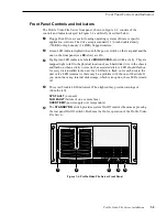
The Profile Video File Server front panel, shown in Figure 1-2, consists of the
controls and indicators keyed to Figure 1-2 and briefly described below.
Ê
Floppy Disk Drive access for loading operating system software or specific
application software. The drive accepts standard 3-1/2-inch double density
(720KB) or high density (1.44MB) floppy diskettes.
Ë
Green LED indicator lighted when both the power switch on the rear panel and the
one on the front panel (see
Î below) are On.
Ì
Eight green LED indicators, labeled
DISK ACCESS
, show disk activity. They are
mapped right to left to the physical location of each hard disk drive in the chassis
and flash on when activity occurs on the associated disk. A LED should flash on
for every disk installed in the unit. If a LED fails to flash on for each disk in the
unit or if a LED remains lit, there may be a problem with the one of the disks. If
you do not have any internal disk storage, which is an option, these LEDs remain
off.
Í
Three red Trouble LED indicators. When lighted they provide warnings of
(from the left):
SYS FAULT
(not used)
FAN FAULT
(failure of one or more fans)
OVER TEMP
(power supply over temperature)
Î
The
STANDBY/ON
switch provides system On/Off control (the same as pressing
the rear panel On/Off switch). Both must be On for operation of the Profile Video
File Server.
Figure 1-2. Profile Video File Server Front Panel
9676-2
1
2
3
4
5
Summary of Contents for PDR 400
Page 4: ...Grass Valley Group Product Support iv Profile Video File Server Installation ...
Page 30: ...Chapter 1 Introduction 1 18 Profile Video File Server Installation ...
Page 66: ...Chapter 2 Mechanical Installation 2 36 Profile Video File Server Installation ...
Page 84: ...Chapter 4 Networking Your Profile System 4 8 Profile Video File Server Installation ...
Page 96: ...Appendix A A 12 Profile Video File Server Installation ...


