background image

                              SignJet JS310 Series Set Up Guide                                  


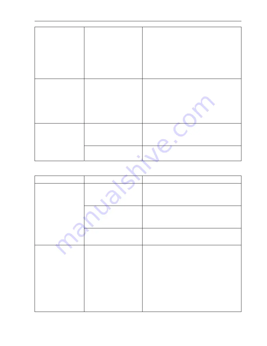
The images overlap. 

The bi-directional band 

adjustment is incorrect. 

Perform the bi-directional band adjustment 

procedure (See section 

VII.10 Bi-directional 

Printing Band Adjustments

).  

If you replace the media with a different type, 

adjust the height of the printheads or change the 

printhead carriage speed, this adjustment 

procedure must be performed.   

There is a lot of blurring 

on the image. 

The heater setting value is 

too low. 

Blurring will occur if the heater setting value is too 

low for the media being used. Raise the setting 

value. 

If phenomena such as the media shifting occur 

and the heater setting value cannot be increased, 

lower the printhead carriage speed. 

The media feed motor is not 

operating. 

Check the selector switch on the media feeding 

system and the direction selector switch setting 

(See section 

VI.1 Media Loading Procedure

). 

The media cannot be 

fed at all. 

The press rollers are raised. Lower the press roller control pole. 


Cleaning cannot be performed


Symptom Cause 

Corrective 

measure 

Insufficient cleaning solution 

in the solution tank. 

Check the level of the cleaning solution in the 

solution tank. If it is low, add some more cleaning 

solution. 

The 3-way valve for the 

cleaning solution tank is 

shut off. 

Move the lever on the 3-way valve to the supply 

position. 

The cleaning solution is 

not being fed. 

There is a bend somewhere 

in the ink supply tube. 

Straighten out the bend. 

Ink is being fed instead 

of cleaning solution. 

The tubes have been 

connected incorrectly. 

Check whether the ink tank and solution tank 

tubes have been connected correctly. 

If they have been connected incorrectly, clean all 

the solution tank tubing and the incorrectly 

connected ink tank tubing, and then feed cleaning 

solution and ink through them once again as 

appropriate.  

Do not mix contaminated cleaning solution with 

fresh cleaning solution.   


- 80 - 

Summary of Contents for SignJet JS310 Series

Page 1: ...SignJet JS310 Series Set Up Guide Version 1 0 ...

Page 2: ...he Printer from its Packaging and the Installation Procedure 18 IV 2 Mounting the Ink Tanks 22 IV 3 Mounting the Waste Ink Tanks 22 IV 4 Connecting the Power Supplies 23 IV 5 Setting the Print Speed 25 IV 6 Executing the Moving Test 25 V Initial Ink Induction Procedure 26 V 1 Initial Cleaning of the Ink Supply Tubes and the Sub Tanks 26 V 2 Initial Cleaning of the Cleaning Solution Supply Tubes 32...

Page 3: ...me Color 61 VII 8 Adjusting the Positions of Printheads of a Different Color 66 VII 9 Media Feed Amount Compensation 68 VII 10 Bi directional Printing Band Adjustments 69 VII 11 Attaching the Printhead Carriage Cover 72 VIII Procedures when leaving the printer for a long time 73 VIII 1 Dispose the ink from the printer 73 VIII 2 Induction of the cleaning solution 74 VIII 3 Moisturizing of print hea...

Page 4: ...e categories before reading the Manual This category provides information that if ignored is highly likely to cause fatal or serious injury to the operator This category provides information that if ignored is likely to cause fatal or serious injury to the operator This category provides information that if ignored could cause injury to the operator or damage to the printer Description of Safety S...

Page 5: ...shock or a fire hazard due to current leakage Clean the power plug before inserting it into the power outlet Do not use the power cable if the plug is damaged Use of a power cable with a damaged plug may result in electric shock or a fire hazard due to current leakage Contact your sales representative or nearest Graphtec vendor and replace the damaged power cable with a new one Make sure that the ...

Page 6: ...ands etc away from the printing panel and the printhead carriage These parts may start to move when data is received and cause injuries Do not disassemble or modify the printer Such actions may result in electric shock or a fire hazard due to current leakage The interior parts of the printer contain high voltage components Contact your sales representative or nearest Graphtec vendor for repairs Do...

Page 7: ...ith any of the internal electrical components may result in a fire hazard or electric shock Use a soft cloth that has been dampened with water or with diluted neutral detergent and then well wrung out to wipe off any dirt Wipe over the same area once again with a dry cloth Never put the ink near open flames Failure to follow this warning might result in fire Do not swallow ink or avoid its splashe...

Page 8: ...unlight or to direct indoor lighting Such actions may cause the sensors to misoperate leading to incorrect printer operation Do not attempt to move the printhead carriage while the printer is turned on Such action may impair the performance of the printer Do not pull on the media or place anything on top of the media while printing is in progress Such actions may impair the performance of the prin...

Page 9: ...ands or any other part of your body wash it off immediately with plenty of water and then consult a doctor Use a forklift equipment to unload the printer The printer weighs approximately 18ES 270 kg 25ES 330 kg There is a risk of lower back injury to the person s attempting to lift the printer Take care not to become trapped under the printer and injured if it tips over while it is being transport...

Page 10: ...the printer in the following temperature and humidity ranges Temperature 20 28 C Humidity 40 70 non condensing CAUTION If the printer is used outside the specified temperature and humidity ranges the print quality may be adversely affected and the printer may malfunction Power Supply Specifications The power supply specifications for this printer are as follows Make sure that the power supply used...

Page 11: ...ain Unit 1 6 2 3 4 5 7 9 10 8 1 LCD Control Panel 2 Press roller control pole 3 Ink tanks Solution tank 4 DRYER Power Socket 5 Take up Roller 6 Vacuum Cleaner 7 Media Feeding Roller 8 Waste Ink Tanks 9 PRINTER Power Socket HEATER Power Socket 10 Media Feeding System 10 ...

Page 12: ...ish 1 17 Maintenance of print head Manual 1 18 Quick Install Manual 1 19 Try Important Setup Sheet 1 20 Waste ink tank 2 21 Bracket Waste ink tank 2 22 φ3 5 Soft tube 1 1 m Spare part 23 φ4 6 Soft tube 1 1 m Spare part 24 Clamp Printhead 10 25 Inlet tube assembly 4 Tube connector for 126 printhead 2 φ3 5 Soft tube 100 mm 2 φ3 5 Soft tube 400 mm F type 3 5 connector Y type 3 way connector 26 Outlet...

Page 13: ... Inner diameter 3 in 32 Packing list 1 33 Jig Head height adjustment 1 34 Tube clamper 8 35 AC Plug 3 250V 36 Media Flange 2 No 1 Printhead No 2 Power cable No 3 USB interface cable No 4 Ink tanks No 5 Solution tank No 6 Screws M4 12 No 7 File bag 12 ...

Page 14: ...ignJet JS310 Series Set Up Guide No 8 Tool box No 9 10 Software CD No 11 Non woven fabric No 12 Sealing washers No 13 Wet keeping frame No 14 Brushes No 20 Waste ink tank No 21 Bracket Waste ink tank 13 ...

Page 15: ... Guide No 22 23 φ3 5 φ4 6 Soft tube No 24 Clamp Printhead No 25 Inlet tube assembly No 26 Outlet tube assembly No 27 Connection cables Printhead No 28 Screws for printhead alignment No 29 Flange Take up roller No 30 Light bulb 14 ...

Page 16: ...SignJet JS310 Series Set Up Guide No 31 Empty core No 33 Jig Head height adjustment No 34 Tube clamper No 35 AC Plug No 36 Media Flange 15 ...

Page 17: ...ys LCD Control Panel Function Keys 1 ONLINE Switch the printer online and offline press down and hold it for several seconds to pause printing 2 ESC Cancel operation and return to upper level menu 3 ENTER Confirm and execute the operation 4 FUNC Shift to special functions combine with key to perform a test print when the printer is waiting Direction Keys Keys Scroll the menus for selection reduce ...

Page 18: ...s of submenu M1 as shown below MENU Ink Status M1 Ch A C M Y K c m Rn_ _ _ _ _ _ _ OFFLINE A1_ _ _ _ _ _ _ On the LCD M1 stands for this submenu under main menu No 1 To return the display to the main menu press the ESC key The arrow points to the first line on the LCD Scroll the submenus by pressing the and keys in the same way as for the main menu A submenu followed by s means that it has no lowe...

Page 19: ...ving the Printer from its Packaging and the Installation Procedure Follow the procedure described below to unpack the printer Function description of the keys Printer fastenings 8 locations Accessories Waste ink tanks IV 1 2 Remove the accessories box and the waste ink tanks 18 ...

Page 20: ... the base used to hold it in place Use a forklift to raise the printer off the base Insert the forklift prongs here CAUTION Before raising the printer align the direction of the wheels with the direction of the rectangular holes If they are not aligned the wheels will catch on the edges of the holes when the printer is raised 19 ...

Page 21: ... s weight is evenly balanced IV 1 5 Move the printer Unlock the casters and then move the printer to its installation location If the installation location is on a different level or if there is a steep slope leading up to it use a forklift or crane to move the printer CAUTION The printer weighs approximately 18ES 270 kg 25ES 330 kg There is a risk of lower back injury to the person s attempting t...

Page 22: ...10 Series Set Up Guide IV 1 7 Remove the plastic sheets and fastening bands Remove the printhead carriage fastening remove the screws CAUTION Store the printhead carriage fastening in a safe place so as not to 21 ...

Page 23: ...t the color of the sticker affixed to the ink tank matches the color of the ring on the ink tube The tube without a colored ring is the tube for the cleaning solution Attach the solution tank to this tube Ring Sticker Mount the ink tanks and the solution tank in the printer IV 3 IV 3 1 Mounting the Waste Ink Tanks Follow the procedure described below to mount the two waste ink tanks Attach the was...

Page 24: ...at were removed from the waste ink tanks in a safe place so as not to lose them IV 4 IV 4 1 Connecting the Power Supplies The printer is provided with three power supplies a printer power supply a heater power supply and a dryer power supply Connect a cable to each power supply making sure that the cable conforms to the specifications Connect the power supply cables to the power supply connectors ...

Page 25: ...pply switch HEATER power supply switch Middle position Forward position DRYER power supply switch Media Feeding System switch IV 4 3 IV 4 4 Insert the plug of each power supply into a power outlet Turn on the cleaner power supply The lower position is the ON position for the power supply The upper or middle position is the OFF position 24 ...

Page 26: ...he ENTER key 3 Select Norm and then press the ENTER key 4 Return to the main menu Executing the Moving Test Execute the Moving Test to ensure that the lubricating oil is spread evenly on the printhead carriage rails and the feed rollers If the power is turned off turn it on Since ink has not yet been supplied to the printer a No Ink alarm will sound after several minutes have elapsed This alarm do...

Page 27: ...and then press the ENTER key 2 From the submenu select Clean Post and then press the ENTER key 3 The printhead carriage moves to the cleaning position and then stops Check that the clips on the sub tanks have been released 1 Open the panel behind the cleaning position 2 Check that the tube clamper on each of the sub tanks is in the open position If any of the clampers is in the closed position ope...

Page 28: ...o ink alarm sounds once again from the main menu select Ink Status and then press the ENTER key once more The alarm will stop sounding when the four sub tanks C M Y K are filled with cleaning solution At this time there will be no operating noise from the ink pump Visually check that the sub tanks are sufficiently filled with cleaning solution The tanks should be filled up to approximately the lev...

Page 29: ...ews at the left and right sides and then remove the cover Screw Screw V 1 7 Remove the printhead protector Pull and then turn about 90 degrees Pull and then turn about 90 degrees Remove V 1 8 Connect the inlet tubes 1 Remove the cover Open the rear panel Remove the screws 28 ...

Page 30: ...s Slide the cover and remove it 2 Remove the fixer Fixer Remove the screws and then remove the fixer Remove the screws 3 Attach the four inlet tubes provided to the 3 way valves on the printhead carriage Inlet tube CAUTION Make sure that the tubes are firmly connected to the 3 way valve 29 ...

Page 31: ...10 V 1 11 Turn on the printer power supply When the power is turned on the printer begins a self test operation the printhead carriage and the feed rollers move When the self test has been completed wait until the main menu is displayed on the LCD Move the printhead carriage to the cleaning position 1 From the main menu select Cleaning Tool and then press the ENTER key 2 From the submenu select Cl...

Page 32: ...r clothing Ink button V 1 13 Empty out the cleaning solution from the ink tanks CAUTION First of all remove the waste ink tanks mounted in the printer and then discard the cleaning solution from the ink tanks into the waste ink tanks V 1 14 V 1 15 Feed out any cleaning solution remaining in the inlet tubes Press the Ink button to feed out any cleaning solution remaining in the inlet tubes When the...

Page 33: ...k and then pour the cleaning solution into the waste ink tank positioned underneath it V 1 17 V 2 V 2 1 Leave the tanks and tubes to dry out Replace the cap on each of the sub tanks and then leave them to dry out for at least 10 minutes Initial Cleaning of the Cleaning Solution Supply Tubes Turn on the printer power supply When the power is turned on the printer begins a self test operation the pr...

Page 34: ...d then press the ENTER key 3 The printhead carriage will move to the cleaning position and then stop Pour approximately 150 cc of cleaning solution into the solution tank Set the Solution valve for the solution tank to the supply position Solution valve Turn to the supply position V 2 5 Set the 3 way valve for each ink tank to the cleaning position Ink solution 3 way valve 4 valves Turn to the cle...

Page 35: ... CAUTION Take care not to get cleaning solution stains on your clothing Solution button V 2 7 Empty out the cleaning solution from the solution tank CAUTION First of all remove one of the waste ink tanks mounted in the printer and then discard the cleaning solution from the solution tank into the waste ink tank V 2 8 Feed out any cleaning solution remaining in the inlet tubes Press the Solution bu...

Page 36: ...e section V 2 Initial Cleaning of the Cleaning Solution Supply Tubes Turn off the printer power supply Turn off the printer power supply before mounting the printheads Performing the printhead mounting operation while the power supply is on may result in damage to the printer or to the printheads Make sure that the power supply is turned off Mount the printheads in order from the left hand side Mo...

Page 37: ...the printhead nozzles Inlet side Outlet side Serial number 2 Attach an outlet tube and tube clamper provided as accessories to the printhead Leave the tube clamper open 3 Remove the cap attached to the printhead and then insert the inlet tube into the printhead inlet Be sure that the tubes are tightly connected to the print heads C M Y K CAUTION Do not mistake the color of tubes 36 ...

Page 38: ...lamp Printhead clamp Check the orientation The longer dimension is the horizontal direction Printhead Top View 5 Loosen the top and left screws and remove the right screw Loosen Remove Loosen 6 Mount the printhead and then replace the right screw 7 Tighten the top left and right screws to fasten the printhead in place 37 ...

Page 39: ...printer power supply When the power is turned on the printer begins a self test operation the printhead carriage and the feed rollers move When the self test has been completed wait until the main menu is displayed on the LCD Since ink has not yet been supplied to the printer a No Ink alarm will sound after several minutes have elapsed This alarm does not indicate a malfunction and no action is re...

Page 40: ...n the outlet tubes Follow the procedure described below to clean the cyan outlet tube Clean the magenta yellow and black outlet tubes in the same way 1 Set the lever of the 3 way valve for the cyan ink tank to the cleaning solution supply position Set the lever on all the other 3 way valves to the ink supply position Cyan Ink solution 3 way valve only All other 3 way valves Turn to the solution su...

Page 41: ...les CAUTION Take care not to get cleaning solution stains on your clothing 5 Replace the outlet tube cap that was removed in Step 2 and then remove the cap from the second outlet tube 6 Press the Solution button in the same way as described in Step 4 to feed cleaning solution through the outlet tube Position the open end of the outlet tube so that it is facing the waste liquid slot Continue to hol...

Page 42: ...the cleaning solution supply position 5 Set the levers on the cyan and magenta 3 way valves to the ink supply position 6 Press the Solution button to feed cleaning solution through the yellow and black printhead nozzles Hold down the Solution button until the cleaning solution flows out of all four printheads V 5 7 V 5 8 Leave the printheads in this status for 10 minutes to ensure that the protect...

Page 43: ... ink stains on your clothing V 6 2 Feed the ink to the sub tanks From the main menu select Ink Status and then press the ENTER key The No ink alarm sounds and then stops and the ink pump operate to feed the ink to the sub tanks If the No ink alarm sounds once again from the main menu select Ink Status and then press the ENTER key once more The alarm will stop sounding when the four sub tanks C M Y...

Page 44: ...be firmly close the tube clamper Make sure not to allow any air to enter the outlet tube Close the tube clamper Close all of 8 caps of outlet tube Y M C K x 2 each tightly using the long nose pliers 5 Replace the outlet tube cap 6 Open the tube clamper on the outlet tube V 6 5 Feed ink through the nozzles Check that all the outlet tube caps have been firmly inserted Close the cap of outlet tube ti...

Page 45: ...wound Print side inside Media Feeding roller Outside wound Media Print side outside Feeding roller CAUTION As the media is heavy at least two persons are required for the loading operation Take care not to drop the roll Dropping the roll on your foot may result in injury VI 1 2 Set Media Flanges 1 Insert the media flange into a media roll 44 ...

Page 46: ...ges when the media may be bended beneath the burden of its weight and then may be wrinkled up after setting media flanges to the heavy media roll VI 1 3 Feed the media a distance of approximately 1 m Use the following procedure to feed the media a distance of approximately 1 m 1 Set the rotation direction switch on the media feeding system Inside wound media direction Outside wound media direction...

Page 47: ...the media has been fed approximately 1 m return the selector switch to the position between the and markings the OFF position Center position VI 1 4 Load media on the platen surface 1 Raise the press roller control pole 2 Remove the screws from the flap at the rear of the printer and open the flap Remove these two screws and open the flap 46 ...

Page 48: ...scales at the left of the printer making sure that the media is not loaded at an angle 5 Lower the press roller control pole to hold the media in place 6 Close the flap and Replace the screws to the flap at the rear of the printer 7 Align the media edge guards with the left and right edges of the media Slide each media edge guard to approximately the position indicated by the dotted line 47 ...

Page 49: ...just before the media reaches the floor return the selector switch to the position between the and markings the OFF position 2 Place the empty core provided on top of the media as shown 3 Use a screwdriver to turn the trimmer fully to the left The orange LED goes out only the green LED remains lit 4 Gradually return the trimmer to the right Stop at the position where the orange LED lights LED Grad...

Page 50: ...ition where the orange LED does not light and then return the selector switch to the position between the and markings the OFF position 7 Check that the orange LED does not light even if an object is placed behind it Sensor Check that the orange LED does not light even if an object is placed behind the sensor Place an object here to check the sensor Feeding roller Media Empty core 8 Check that the...

Page 51: ... the take up core 1 Raise the take up roller at the left hand side and remove it 2 Slide one of the flanges onto the roller and then fasten it in place at the right Use these two screws to fasten the flange 3 Insert the take up core onto the right flange 4 Insert the other flange into the left edge of the take up core 50 ...

Page 52: ...tch to the position between the and markings the OFF position Center position 2 From the main menu select Print Para and then press the ENTER key 3 From the submenu select Print Post and then press the ENTER key 4 While holding down the FUNC key press the key to feed the media 5 When the media has reached the take up roller position with a little extra length added to facilitate the take up operat...

Page 53: ...ia width Loosen the flange screws and align the take up core with the width of the media Loosen these two screws VI 2 4 Use a length of tape to attach the leading edge of the media to the take up core VI 2 5 Place an empty core on top of the media to provide winding tension 52 ...

Page 54: ...n the trimmer to the right Stop at the position where the orange LED lights 4 Check that the media stops at the sensor after it has been automatically taken up Set the selector switch on the take up unit to Auto Left hand position 5 Check that the media is not taken up when an object is placed in front of the sensor Sensor The take up roller does not take up the media even when an object is placed...

Page 55: ... Select ON and then press the ENTER key Detect the media width 1 Raise the pinch rollers and then lower them 2 The loaded media is detected and the following screen appears 3 Press the ENTER key to start the media detection operation 4 When the media has been detected OK is displayed on the screen If you want to cancel the media detection operation press the ESC key If the printer was not able to ...

Page 56: ... then turn on the power supply EF data sheet EF value Recommend EF Data Serial number Printhead package 1 From the main menu select Print Para and then press the ENTER key 2 From the submenu select PH Volt Set and then press the ENTER key 3 Enter the EF values for PH1 to PH8 and then press the ENTER key CAUTION Enter the Recommend EF Data when you register it into your printer Example If the Recom...

Page 57: ...tup Graphtec V folder Choose the Destination Location At the following screen specify the destination folder and then click Next VII 2 4 Select the Setup Type Select the setup type and then click Next Typical Installs the Program Files Samples and USB Components files Recommended Compact Installs the Program Files files Custom Installs the files selected from Program Files Samples Card Components ...

Page 58: ...allation procedure If you selected Custom for the Setup Type insert a check only for the files that you want to install VII 2 6 Close the InstallShield Wizard to complete the installation When installation has been completed the following screen appears Before you can use the Try utility you must restart your computer Select Yes I want to restart my computer now and then click Finish 57 ...

Page 59: ...0 Connection Use the USB cable provided to connect the printer s USB port directly to the computer s USB port Connecting the Printheads Turn off the printer power supply Connect the printhead cables provided Printhead connectors Printhead carriage PCB connectors VII 4 3 Attach the fixer and cover Put the cable through a guide Tighten the screws Fixer Tighten the screws Cover 58 ...

Page 60: ...y CAUTION Remove the wet keeping frame before turn on the power supply VII 5 2 Launch the Try program Select Try from Programs in the Start menu VII 5 3 Specify the printer you will use When using this software for the first time a printer must be selected Select JS310 from Printer on the menu bar JS310 59 ...

Page 61: ...tory printing no non firing nozzles Please refer to the file SIGNJET Set Up Guide_en_ver pdf which is saved in the JS310 CDM01E CD ROM VII 6 2 Perform printhead cleaning 1 From the main menu select Cleaning Tool and then press the ENTER key 2 From the submenu select Clean Post and then press the ENTER key 3 The printhead carriage moves to the cleaning position 4 Check that the levers on the 3 way ...

Page 62: ...ds Select the print mode 1 Press the ONLINE key on the control panel to put the printer into ONLINE status 2 On the menu bar click File Print Setup 3 Make the following settings Insert a check in the box in front of Color C Cyan Remove the checks from the boxes in front of the other three colors Color M Magenta Color Y Yellow and Color K Black Select Test Mode for Print Mode Remove the check from ...

Page 63: ...on the toolbar to print the selected pattern Only cyan will be printed If you want to suspend the printing operation press the ESC key Torestart printing select Continuous from the menu displayed on the printer s LCD and then press the ENTER key If you want to quit the printing operation select Cancel from the menu displayed on the printer s LCD and then press the ENTER key 62 ...

Page 64: ... not vertical adjust the screws used to fasten the print heads The line printed by the print head of rear 1 scan width The line printed by the print head of front Left screw Right screw Print Head 3 2 1 Upper screw How to tilt the printing line in anticlockwise direction Loosen a right screw and then tighten a left screw How to tilt the printing line in clockwise direction Loosen a left screw and ...

Page 65: ...e More button The Warning Change these parameters carefully message is displayed Click Yes Change the settings in accordance with the printed results The line printed by the print head of rear The line printed by the print head of front Adjust these values to move horizontal printing position of the front print head Increasing the value Print position is moved to right Decreasing the value Print p...

Page 66: ...per screw How to up the printing line Loosen an upper screw and then tighten a left and a right screws How to down the printing line Loosen a left and a right screws by the same rotation and then tighten an upper screw Print the adjustment pattern once again and check the results of the adjustments made Repeat the printing and adjustment procedures until the positions of the vertical and diagonal ...

Page 67: ...ay Select the print mode 1 Press the ONLINE key on the control panel to put the printer into ONLINE status 2 On the menu bar click File Print Setup 3 Make the following settings Insert a check in the boxes in front of Color C Cyan and Color M Magenta Remove the checks from the boxes in front of Color Y Yellow and Color K Black Select Test Mode for Print Mode Remove the check from the box in front ...

Page 68: ...lines with the cyan lines 5 Increase or decrease the setting values until the magenta lines are aligned on top of the cyan lines Adjust the magenta line to on the cyan line Adjust the horizontal space for the front head and rear head of magenta At this time increase and decrease the adjustment value of a front head and rear head at equal value Adjust the vertical space for the head of magenta VII ...

Page 69: ... the menu bar click File Print Setup 3 Make the following settings Insert a check in the box in front of Color C Cyan Remove the checks from the boxes in front of the other three colors Color M Magenta Color Y Yellow and Color K Black Select Test Mode for Print Mode Remove the check from the box in front of BiDirection 4 Click OK to close the dialog box VII 9 2 Select an adjustment pattern and pri...

Page 70: ...de Repeat the printing and adjustment procedures until satisfactory adjustment results have been achieved Bi directional Printing Band Adjustments The bi directional band adjustment settings need to be changed if changes are made to the following two parameters Whenever these parameters are changed make the adjustment settings accordingly 1 The printhead carriage speed 2 The media thickness The fo...

Page 71: ...ont of Color C Cyan Remove the checks from the boxes in front of the other three colors Color M Magenta Color Y Yellow and Color K Black Select Test Mode for Print Mode Remove the check from the box in front of BiDirection 4 Click OK to close the dialog box VII 10 2 Select an adjustment pattern and print it 1 On the menu bar click File Open 2 Open the C Try SmallGrid126 group file 3 Click the butt...

Page 72: ...lines printed on the outward and return passes form straight lines in the vertical direction 1 On the Try menu bar click File Print Setup 2 Click the More button 3 The Warning Change these parameters carefully message is displayed Click Yes 4 Perform adjustments accordingly while viewing the printed results Print direction Printed from the right Printed from the left Return pass 71 ...

Page 73: ...t Setup menu to align the printed bands VII 10 4 VII 10 5 VII 11 Print the adjustment pattern once again and check the results of the adjustments made Repeat the printing and adjustment procedures until the vertical lines printed on the outward and return passes form continuous straight lines Make adjustments in the same way for the magenta yellow and black printheads Attaching the Printhead Carri...

Page 74: ...of all remove the waste ink tanks mounted in the printer and then discard the ink from the ink tanks into the waste ink tanks VIII 1 4 VIII 1 5 VIII 1 6 Feed out any ink remaining in the PrintHead nozzles Press the Ink button to feed out any ink through the PrintHead nozzles When the No ink alarm sounds from the main menu select Ink Status and then press the ENTER key to continue the ink removal o...

Page 75: ...ill be no operating noise from the ink pump Move the printhead carriage to the cleaning position 1 From the main menu select Cleaning Tool and then press the ENTER key 2 From the submenu select Clean Post and then press the ENTER key 3 The printhead carriage moves to the cleaning position and then stops Feed out any cleaning solution through the PrintHead nozzles Press the Ink button to feed out a...

Page 76: ...tanks and the solution tank CAUTION First of all remove the waste ink tanks mounted in the printer and then discard the cleaning solution from the ink tanks and the solution tank into the waste ink tanks IX 1 4 Empty out the cleaning solution from the sub tanks CAUTION First of all remove the waste ink tanks mounted in the printer and then discard the cleaning solution from the sub tanks into the ...

Page 77: ...nt head then fixing with some adhesion tape to resist movement Discard the waste ink Remove the tubes from the waste ink tanks Take out the waste ink tanks from the printer Displace the waste ink to the plastic bottle that you provided CAUTION Do not mix the waste ink with any other chemicals and solvent when you displace the waste ink Also dispose the waste ink as the industrial waste waste oil I...

Page 78: ...hen turn the power off and back on again Unsatisfactory printing Symptom Cause Corrective measure Insufficient ink If the No ink alarm sounds refill the ink tank s and then press the ESC key Clogged nozzles Print the nozzle check pattern to check the nozzles See section VII 6 Printing the Nozzle Check Pattern If there are several clogged nozzles perform a printhead cleaning operation Dirty nozzle ...

Page 79: ... each tank Whether the colored rings on the tubes and the stickers on the ink tanks are the same color Whether the inlet tubes have been connected correctly If an error was made with any of the above use cleaning solution to wash out all the affected tanks tubing and then refill the tanks with ink of the correct color or re feed ink through the tubes as required Cleaning solution is being emitted ...

Page 80: ...sure to use the drying fan If the data has a high printing density the drying time may not be sufficient Choose one of the following solutions Reduce the printing density of the data Reduce the printhead carriage speed Increase the number of passes Incorrect feed adjustment Perform the feed adjustment procedure described in this manual See section VII 9 Media Feed Amount Compensation Incorrect pri...

Page 81: ... See section VI 1 Media Loading Procedure The media cannot be fed at all The press rollers are raised Lower the press roller control pole Cleaning cannot be performed Symptom Cause Corrective measure Insufficient cleaning solution in the solution tank Check the level of the cleaning solution in the solution tank If it is low add some more cleaning solution The 3 way valve for the cleaning solution...

Page 82: ...section VII 6 Printing the Nozzle Check Pattern The media jammed The gap between the media and the printheads was insufficient causing the media to touch the printheads Raise the height of the printheads Perform a printhead cleaning operation See section VII 6 Printing the Nozzle Check Pattern The switch setting is incorrect See section VI 2 Winding the Media onto the Take up Unit in this manual f...

Page 83: ...The specifications etc in this manual are subject to change without notice JS310 UM 851 August 24 2006 1st GRAPHTEC CORPORATION ...

Reviews: