Combi V3, Combi Max and Vortex Combi models
26
5 - GENERAL BOILER INFORMATION
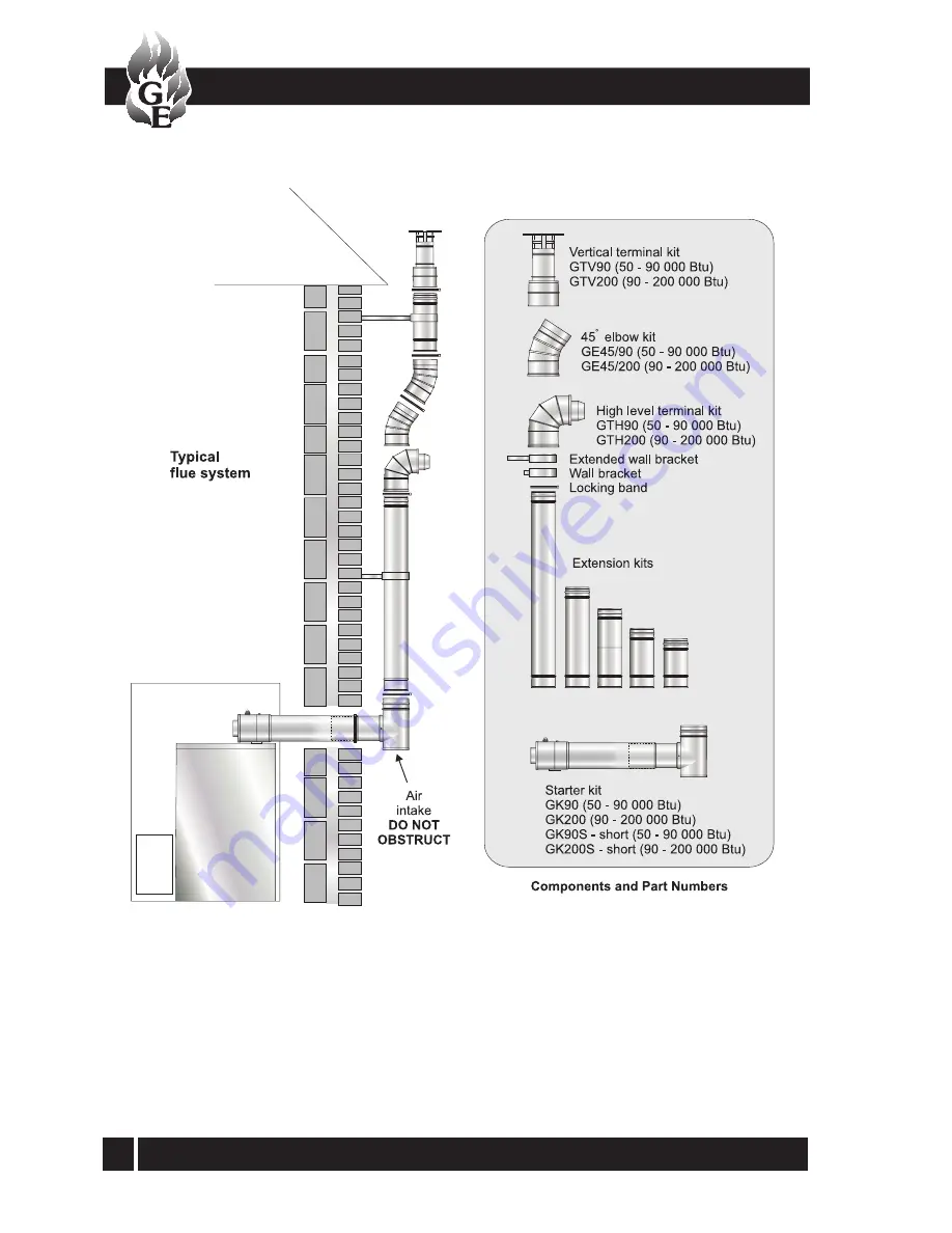
Fig. 14 - External flue (Green system)
Page 1: ...Combi Kerosene only Part No DOC 56 Rev 03 September 2005 This appliance is deemed a controlled service and specific regional statutory requirements may be applicable After installing the boiler leave...
Page 2: ...ser 43 10 Boiler servicing 43 11 Boiler components 47 12 Wiring diagrams 49 13 Fault finding 52 14 Burner spares 59 15 Health and safety information 61 16 EC declaration of conformity 62 LIST OF CONTE...
Page 3: ...radiators or the hot water via the hot water heat exchanger The boiler thermostat has an operating range of 75 C to 85 C For optimum hot water operation ensure this is set to maximum To ensure that th...
Page 4: ...l only provide central heating during the on periods set on the timer When set to OFF the boiler will not provide central heating When set to CONSTANT the boiler provides central heating continuously...
Page 5: ...5 Combi V3 Combi Max and Vortex Combi models Fig B Boiler controls Vortex Combi 36 shown Fig A Combi V3 and Combi Max boiler Controls 3 COMBI V3 COMBI MAX and VORTEX COMBI USER INSTRUCTIONS...
Page 6: ...ff the electricity supply to the boiler and contact your Service engineer The boiler will supply domestic hot water whenever a hot tap is opened providing the Boiler On Off switch is set to ON Note Th...
Page 7: ...aseofacontrolmalfunction causingoverheating Aredneon seeFig AorB will light indicating the thermostat has operated If your boiler goes off and you try to light it but nothinghappensandthe Lock out res...
Page 8: ...e gal Weight dry kg lb Max heat input Kerosene kW Btu h Connections Heating flow and return Cold water mains inlet Domestic hot water outlet Pressure relief valve discharge Flue size conventional Wate...
Page 9: ...ater outlet Pressure relief valve discharge Condensate connection Flue size conventional Waterside resistance Flow Return temp diff of 10 C Waterside resistance Flow Return temp diff of 20 C Boiler th...
Page 10: ...d the air damper must be adjusted to obtain the correct CO2 level and the Installer must amend the data label 4 BOILER TECHNICAL INFORMATION Combi V3 and Combi Max oil boilers using class C2 kerosene...
Page 11: ...the boiler to be commissioned and serviced the boiler is supplied with a combustion test point on the front cleaning door When this test point is used please note the following 1 The test point is fo...
Page 12: ...t water heat exchanger Pump Automatic air vent Boiler Heating return Heating flow Expansion vessel Primary store Pressure relief valve Drain cock Pressure switch Check valve Fig 1 Note Water connectio...
Page 13: ...13 Combi V3 Combi Max and Vortex Combi models 4 BOILER TECHNICAL INFORMATION Fig 3a Vortex Combi 36 dimensions Fig 3 Vortex Combi 26 dimensions Boiler dimensions Vortex Combi 4 9...
Page 14: ...Combi V3 Combi Max and Vortex Combi models 14 4 BOILER TECHNICAL INFORMATION Fig 4 Water schematic of boiler Vortex Combi 4 10...
Page 15: ...vely an external timer located remotely from the boiler in a convenient position for the user may be connected to the boiler for this purpose the Grant TCR kit Part No TCRKIT is ideal Refer to Section...
Page 16: ...RMATION IMPORTANT Before starting any work on the boiler or fuel supply please read the health and safety information given in Section 15 on page 61 Regional statutory requirements may deem thisapplia...
Page 17: ...tank The pipe ends should be a sufficient distance apart so as to preventanysedimentdisturbedbythereturnentering the supply pipe 2 Avoid the bottom of the tank being more than 3 m below the burner 3 A...
Page 18: ...valve as shown in Fig 7 Refer to the manufacturers instructions supplied with the Tiger Loop The Tiger Loop must be mounted vertically 5 GENERAL BOILER INFORMATION Note To prevent any possibility of...
Page 19: ...return connection of the pump and fit the By pass screw using an hexagonal key 5 Connect the return oil flexible fuel line to the pump 6 Connect the 3 8 to 1 4 BSP adaptor to the flexible fuel line 7...
Page 20: ...em checks must be carried out Short circuit Polarity Earth continuity and Resistance to earth 5 GENERAL BOILER INFORMATION See Figs 10 and 11 A sufficient permanent air supply to the boiler should be...
Page 21: ...bove the ridge level will normally provide the necessary draught of at least 8 7 N m2 0 035 in wg as measured close to the boiler connection If a draught of 37 N m2 0 15 in wg or more is measured then...
Page 22: ...iler cleaning door Combi 90 V3 and Combi Max and on top of the Combi 70 V3 boiler Conventional flue system Vortex Combi 5 7 Fig 12 Typical conventional flue with brick chimney 5 GENERAL BOILER INFORMA...
Page 23: ...idflueisusedexternally itmustbeofthetwinwall typeincorporatingseals musthaveastainlesssteelinner skin and be suitably insulated and weather proofed Fig 13 Vortex Combi typical conventional flue with b...
Page 24: ...90 elbow should be fitted per system IMPORTANT For Vortex Combi boilers with the flue to the left hand side leave a minimum gap of 150 mm between the side of the boiler and the wall to accommodate th...
Page 25: ...access the terminal must be protected by a guard The guard must be fitted centrally over the flue terminal and securely fixed to the wall The low level balanced flue Yellow system is supplied with a...
Page 26: ...Combi V3 Combi Max and Vortex Combi models 26 5 GENERAL BOILER INFORMATION Fig 14 External flue Green system...
Page 27: ...as an openable window or a permanent opening such as a permanently open air vent 2 Notwithstanding the dimensions given a terminal should be at least 300 mm from combustible material e g a window fram...
Page 28: ...5 GENERAL BOILER INFORMATION Boiler location 5 10 IMPORTANT All pipes to be fitted into the push fit connectors provided should be cut using a pipe slicer or pipe cutter to leave the pipe ends with a...
Page 29: ...of the expansion vessel 5 GENERAL BOILER INFORMATION 4 The system design pressure cold should be between 0 5 and 1 0 bar This pressure is equivalent to the maximum static head see Fig 16 in bar 0 3 1...
Page 30: ...ated to reduce heat loss 4 All taps and mixing valves used in the domestic hot water system must be suitable for operating at a mains pressure of up to 8 bar 5 If required a shower may be fitted in th...
Page 31: ...moval of the condensate Condensate can be disposed either internally into an internal domestic waste system or directly into the soil stack or externally to an external soil stack gully hopper or soak...
Page 32: ...ate soakaway On external discharge systems to a gully or soakaway the bung should be removed from the overflow outlet If connected to an external soil stack the bung must be fitted on the trap If ther...
Page 33: ...re does not exceed 65 C Whenthehottapisclosedandtheflowswitchsensesthat hot water is no longer required the Hot Water pump will continue to run and the burner continues to fire until the primary store...
Page 34: ...a Note Dimension B given in Fig 20a includes an extra 10 mm over the size of the terminal to provide clearance for fitting 5 GENERAL BOILER INFORMATION Fig 20a Low level balanced flue Yellow system an...
Page 35: ...Adjustable sections The adjustable extensions are telescopic The wall terminal section is adjustable and is suitable for a wall thickness of 215 mm to 450 mm Simply adjust to the required length using...
Page 36: ...e safety valve discharge pipe must be routed clear of the boiler to outside to discharge in such a manner that it can be seen but cannot cause injury or damage to persons or property 7 Do not turn on...
Page 37: ...The charge pressure must not be less than the actual static head at the point of connection Do not pressurise the vessel above 1 5 bar The air pressure in the vessel must be checked annually The cent...
Page 38: ...viously removed 5 Ensurethatallexternalwiringisadequatelysupported 6 Do not switch on the electricity supply at this stage 6 BOILER INSTALLATION Important Ensure electrical supply to boiler has been i...
Page 39: ...2 Connecttheflexiblefuellinetotherigidsupplyusing the adaptor supplied The supply enters through one of the holes at the bottom of the case sides Connect the fuel supply 6 10 Fig 24 RDB burner compone...
Page 40: ...ug from the centre of the pump Using a suitable screwdriver rotate the exposed spindle about one turn When water starts to trickle out replace the plug On the Vortex Combi the Hot water pump must also...
Page 41: ...following commissioning procedure is carried out to ensure safe and efficient operation of the boiler Note Check that the baffles are in position and that the cleaning cover is correctly fitted and a...
Page 42: ...st point is provided This is located in the cleaning door on the front of the Combi 90 V3 Combi Max and Vortex Combi and on the top of the Combi 70 V3 13 After allowing the burner to run for 20 minute...
Page 43: ...tions and usage but in general once per year should be adequate Servicing and replacement of parts must only be carried out by a suitably qualified engineer Important Detailsofeveryserviceshouldbereco...
Page 44: ...urner identify mark if necessary which is the inlet and return if they are to be disconnected 4 Check the condition of the flue clean as necessary 5 Checktheconditionofthefrontcleaningdoorsealon the C...
Page 45: ...ervewhether the water discharges from the 22 mm condensate outlet Replace the turbulators 8 All boilers Replace the cleaning door or cover securing it in position with the nuts and washers previously...
Page 46: ...rrect size and type refer to tables in Section 4 3 4 4 or 4 6 and boiler data label Do NOT attempt to clean the nozzle Remove and replace the nozzle using a good fitting spanner 16mm Theuseofanill fit...
Page 47: ...ting return isolating valve S Pressure switch Connections 1 Diverter valve cold water inlet 2 Diverter valve primary inlet 3 Diverter valve primary outlet 4 Plate heat exchanger hot water outlet 5 Col...
Page 48: ...turn 15 Non return valve x 2 Connections pipe A Heating system flow push fit elbow B Heating system return push fit elbow C Cold water inlet push fit elbow D Hot water outlet push fit elbow E Pump iso...
Page 49: ...D Y Y BR BR BR Electonic PCB board BLK Y OR 1 2 3 4 Chassis earth to bolt in boiler casing Chassis earth to bolt in boiler casing Pressure switch neon amber Overheat stat neon red Limit stat G Y RD BL...
Page 50: ...e islolator with power on indicator Remove link 8 to 9 yellow if timer is fitted Frost thermostat if fitted If room thermostat is fitted remove link 4 to 5 and connect room thermostat in its place Cha...
Page 51: ...t incorporating voltage free output contacts Connection of Grant remote wall mounted mini programmer 12 6 Grant programmable room thermostat 12 7 A programmable room thermostat Part No RSKIT is availa...
Page 52: ...tat to maximum Set 3 position Heating switch to Constant Check and reset thermostat as necessary Check for 230 V output from BURNER LIVE terminal of PCB Check continuity of overheat thermostat replace...
Page 53: ...ue is clean and unobstructed rectify as necessary Check flue draught and improve flue as necessary Check flue condition size and alter as necessary Check as for high smoke number above Check that an e...
Page 54: ...ck and rectify as necessary Check and rectify as necessary Check flow is at least 3 litres min rectify as necessary Check and rectify as necessary Check hot and cold inlets are connected correctly Che...
Page 55: ...exchanger is sooted up Check setting and set to Constant to test Check power supply to timeswitch Check and replace if necessary Check continuity of switch replace if necessary Check continuity of wi...
Page 56: ...d Burner oil pressure set too low on oil pump Incorrect nozzle fitted to burner POSSIBLE CAUSE Check and rectify as necessary Open all valves in pipework to and from boiler Open valve fully located in...
Page 57: ...ry Check links are fitted between terminals 4 5 and 8 9 Replace sensor and check operation Check for 230 V output from BURNER LIVE terminal If no 230 V output replace PCB Check for 230 V supply to bur...
Page 58: ...Combi V3 Combi Max and Vortex Combi models 58 13 FAULT FINDING Riello RDB burner fault finding 13 7...
Page 59: ...BS116 10 Fan 70V3 90V3 and Vortex 26 3005708 RBS39 10 Fan Vortex 36 3008645 RBS142 10 Fan Max 3005788 RBS151 11 Photocell 3008646 RBS115 Key No Description Riello Part No Grant Part No Key No Descript...
Page 60: ...Combi V3 Combi Max and Vortex Combi models 60 14 BURNER SPARE PARTS Burner Heads...
Page 61: ...al Types Silicone elastomer Description Sealant and adhesive Known Hazards Irritation to eyes Precautions Avoid inhalation of vapour contact with eyes and prolonged or repeated contact with skin After...
Page 62: ...ents of the following European Directives 1 89 336 EEC Electromagnetic Compatibility Directive Referred to the generic standards EN 55014 1993 EN 50082 1 1992 2 73 23 EEC Electrical Equipment Safety R...
Page 63: ...63 Combi V3 Combi Max and Vortex Combi models...
Page 64: ...r appearances are changed in the interests of continued product improvement All goods sold are subject to our official Conditions of Sale a copy of which may be obtained on application Grant Engineeri...